Regent Sheffield FCTWL65 User Manual
Page 3
• Fixture must be connected to a 120 Volt, 60 Hz power source. Any other
connection voids the warranty.
• Keep away from flammable objects.
• The e l e c t rical system, and the method of electrically connecting the fixture to it,
must be in accordance with the National Electric Code and local building codes.
• Disassembly of the fixture will void the warranty.
• Use only a 65 watt, PL type fluorescent bulb. Use of any other bulb will
damage the fixture and void the warranty.
• Fixture must be connected to a 120 Volt, 60 Hz power source. Any other
connection voids the warranty.
• Keep away from flammable objects.
• The electrical system, and the method of electrically connecting the fixture to
it, must be in accordance with the National Electric Code and local building
codes.
• Disassembly of the fixture will void the warranty.
• Use only a 65 watt, PL type fluorescent bulb. Use of any other bulb will
damage the fixture and void the warranty.
WARNING: Deviation from the assembly instructions may result in a risk of fire
or electric shock.
SAVE THESE INSTRUCTIONS
Important: Read Before Using!
Remove cardboard insert that is protecting bulb before use.
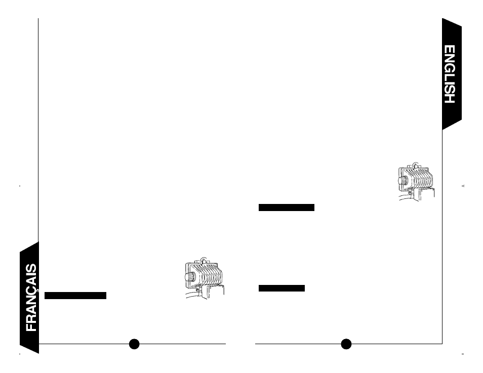
Step 1: Loosen the knob (turn counter-clockwise) located
on the back and top of the fixture (C).
Step 2: The doorframe and lens assembly will swing down
allowing access to the bulb. Remove the card-
board insert.
Step 3: Replace the door frame and lens assembly and
secure it by tightening the knob that was loosened
in Step 1.
Step 1: Slide the upper handle with foam grip into the tube on the U-brac ket
which is located on the bottom of the fixture housing.
Step 2: Align the threaded screw holes in the handle with the two holes in the
tube and secure with the two screws provided.
Step 3: Slide the end of the “S” stand, with the screw hole in it, into the
remaining open end of the tube on the U-bracket located on the bot-
tom of the fixture housing.
Step 4: Align the threaded screw hole in the stand with the slotted hole in the
tube and secure with the knob provided. NOTE: First, slip the plastic
spacer over the screw that extends from the knob, making sure that
the flat side of the spacer rests against the knob itself. The curved
side of the spacer will rest against the curvature of the stand as the
knob is tightened down.
Step 1: Loosen the knob (turn counter-clockwise) located on the back and top
of the fixture (C).
Step 2 The doorframe and lens assembly will swing down allowing access to the
bu l b. R e m ove the new fluorescent bulb from its pack a g e.
Step 3: Push one of the plastic bulb retainer clips open and carefully insert
the bulb under this retainer clip. Repeat the process on the opposite
side, then push the bulb into the bulb socket. (D) NOTE: Be careful
not to damage the bulb.
Installing the bulb
Assembling the fixture
10
férences nuisibles dans une installation résidentielle. Cet équipement
produit, utilise et peut émettre de l’énergie en fréquence radio. S’il
n’est pas installé et utilisé conformément aux instructions, il peut
provoquer des interférences nuisibles aux communications radio.
Cependant, il n’existe aucune garantie qu’une installation quelconque
ne produira pas d’interférence. Si cet équipement cause des inter-
férences nuisant au fonctionnement d’un appareil radio ou d’un
téléviseur (ce qui peut être déterminé en activant/désactivant
l’équipement), l’utilisateur est encouragé à éliminer les interférences
en appliquant l’une des mesures suivantes :
- Réorientez ou déplacez l’antenne réceptrice.
- Augmentez l'espace entre l'équipement et le poste récepteur.
- Branchez l'équipement sur une prise ou un circuit ne servant pas
au poste récepteur.
- Demandez l'aide de votre marchand ou d'un technicien expéri-
menté en radio/télévision.
• Le dispositif doit être branché à une source d’énergie de 120 Volts,
60 Hertz. Tout autre branchement que celui-ci annule la garantie.
• Gardez éloigné de tout objet inflammable.
• Le système électrique et la méthode de raccordement électrique de
l’appareil doivent obéir au code national de l’électricité ainsi qu’aux
règlements de construction locaux.
• Le démontage de cet ensemble annulera la garantie.
• Utiliser uniquement une ampoule fluorescente de type PL, ayant une
puissance de 65 watts. L’utilisation d’une autre ampoule endom-
magerait l’appareil et annulerait sa garantie.
AVERTISSEMENT : Ne pas appliquer les instructions d’assemblage
peut causer un incendie ou un choc électrique.
CONSERVER CES INSTRUCTIONS.
Important : À Lire Avant L’Utilisation !
E n l evez le manchon en carton qui protège l’ampoule avant son utilisation.
Etape 1 : Desserrez la molette (tournez en sens inverse des aiguilles
d’une montre) situé à l’arrière en haut de l’appareil (C).
Etape 2 : Le cadre de porte et l’ensemble de lentilles vont s’abaisser
en basculant en donnant accès à l’am-
poule. Ôtez l’intercalaire en carton.
Etape 3 : Refermez le cadre de porte et l’ensemble
de lentilles et fixez-les en place en resser-
rant la molette qui avait été desserrée
précédemment.
Etape 1 : Glissez la poignée supérieure avec prise en mousse dans le
tube sur le support en U qui est situé en bas du caisson de
l’appareil.
Etape 2 : Alignez les trous filetés pour vissage de la poignée avec les
deux trous dans le tube et bloquez avec les deux vis fournies.
Assemblage de l’appareil
1
3
(C)
(C)