Roberts Gorden Vantage TF TF-300 User Manual
Page 7
SECTION 1: H
EATER
S
AFETY
1
SECTION 1: HEATER SAFETY
Your Safety is Important to Us!
This symbol is used throughout
the manual to notify you of possi-
ble fire, electrical or burn hazards.
Please pay special attention when
reading and following the warn-
ings in these sections.
Installation, service and annual inspection of heater
must be done by a contractor qualified in the
installation and service of gas-fired heating
equipment.
Read this manual carefully before installation,
operation or service of this equipment.
This heater is designed for heating nonresidential
indoor spaces. Do not install in residential spaces.
These instructions, the layout drawing, local codes
and ordinances, and applicable standards that apply
to gas piping, electrical wiring, venting, etc. must be
thoroughly understood before proceeding with the
installation.
Protective gear is to be worn during installation,
operation and service. Thin sheet metal parts,
including the aluminum reflector portion of the heater
and the various venting components, have sharp
edges. To prevent injury, the use of work gloves is
recommended. The use of gloves will also prevent
the transfer of body oils from the hands to the surface
of the reflector.
Before installation, check that the local distribution
conditions, nature of gas and pressure, and
adjustment of the appliance are compatible.
For additional copies of the Installation, Operation
and Service Manual, please contact Roberts-Gordon
LLC.
1.1 Manpower Requirements
To prevent personal injury and damage to the heater,
two persons will be required for installation.
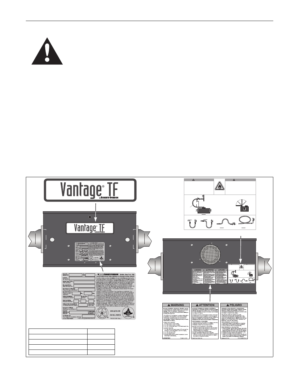
1.2 Safety Labels and Their Placement
Product safety signs or labels should be replaced by
the product user when they are no longer legible.
Please contact Roberts-Gordon or your ROBERTS
GORDON
®
independent distributor to obtain
replacement signs or labels. See Page 1, Figure 1
through Page 2, Figure 2
.
FIGURE 1: Top and Bottom Panel Label Placement
Logo Label
Rating Plate Label
Bottom
Panel
Gas Connection Label
Lighting Instruction Plate Label
Top Panel
Printed in the U.S.A/Imprimé aux Etats-Unis
P/N 91018124 Orig.
www.rg-inc.com
WARNING
Risque d’incendie
Serrez et installez les raccords de canalisation de gaz pour
relier la source de gaz selon l'exemple.
Le ligne de gaz de câble peut se fissurer une fois tordue.
Le ligne de gaz se déplace pendant l'exécution normale.
Utilisez seulement un connecteur de ½" ou de ¾" en
diamètre interne nominal et d’une longeur de 36" (91 cm).
Le connecteur est fourni avec le chauffage pour les
modèles américains (Pas avec les modèles canadiens).
Le non-respect de ces consignes peut causer la mort, les
blessures ou le dommage matériel.
© 2009 Roberts-Gordon LLC
INCORRECT POSITIONS / POSITION INEXACT
Horizontal/
Vue de côte
End View/Vue arrière
Vertical
(as shown left)/
(montrée à gauche)
Alternate
positions okay/
Positions
alternatives
sont bien
Fire Hazard
Tighten and install gas hose fittings to connect gas
supply according to example below.
Gas hose can crack when twisted.
Gas hose moves during normal operation.
Use only 36" (91cm) long connector of 1/2" or 3/4"
nominal ID.
Connector supplied with heater for U.S. models (not with
Canadian models).
Failure to follow these instructions can result in death,
injury or property damage.
CORRECT POSITIONS / POSITION EXACT
Heater Movement/
Mouvement d'appareil de
chauffage
Heater Movement/
Mouvement d'appareil de
chauffage
Heater Movement/
Mouvement d'appareil de
chauffage
Heater Movement/
Mouvement d'appareil de
chauffage
ATTENTION
Shut-Off Valve must be parallel to burner
gas inlet. The 3" (8 cm) displacement
shown is for the cold condition. This
displacement may reduce when the system
is fired.
Le Robinet d’arrêt doit être parallèle au
tube d'admission de gaz du brûleur. Le
déplacement de 3"(8 cm) montré est quand
le système est froid. Ce déplacement peut
diminuer quand le système est activé.
Shut-Off Valve (Included With Gas Hose)/
Robinet d’arrêt (Fournie avec le raccordement)
Heater Movement/Mouvement d'appareil de chauffage
Flexible Gas Hose 36"
(91 cm) length/
Flexible de Raccordement
de Gaz en Acier Inoxydable
de longuer 36" (91 cm)
12"
(30 cm)
3" (8 cm)
max. displacement/
déplacement maximum
Side View/Vue de côté
45°
45°
3/4" NPT
Pipe/Tuyau
90° Pipe Elbow (Not Included)/
Coude á 90° (Non Inclus)
Description
Part Number
Logo Label
91013202
Rating Plate Label
91010401
Gas Connection Label
91018124
Lighting Instruction Plate Label
91029602