Installation diagrams, Examples only) independent installation, Figure 6 – Lifebreath 200ERVD User Manual
Page 20: Figure 7
20
ERV
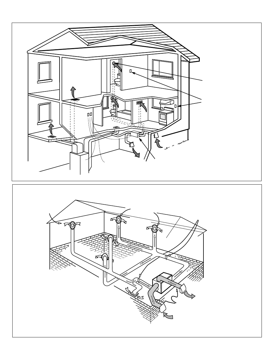
Figure 6
Installation Diagrams
(Examples Only)
Independent Installation
Adjustable fresh
air supply
Adjustable damper for
balancing air flow in and
out of the house
Adjustable stale
air return
Fresh air
supply hood
Stale air
exhaust hood
Flexible insulated ducting
with a vapour barrier
Note:
• ERV exhausts from kitchen and /or bathrooms
or other central location to outdoors
• ERV supplies outdoor air directly to each bedroom,
to each floor without a bedroom and to the principal living areas
• ERV shown is for illustrative purposes only. Actual port location
varies depending on model. See schematic diagrams on page 4.
Figure 7
Round adjustable
TECHGRILLES
Optional controls for
intermittent high speed
Optional control
ERV access door
(on back of unit)