Front and rear controls – Nady Systems SPA 1400 User Manual
Page 4
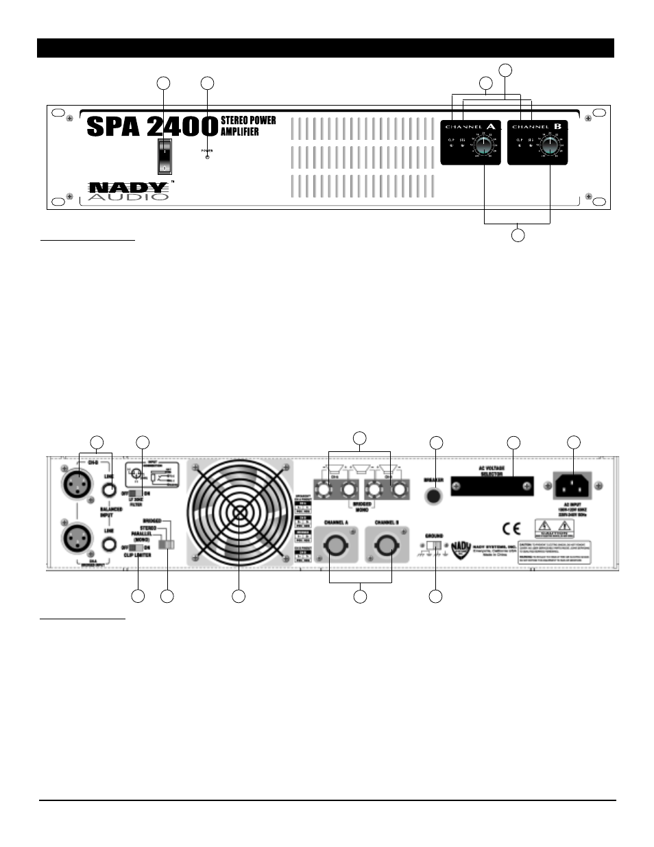
1. POWER
SWITCH
To turn the unit ON or OFF, press the upper or lower
portion of this button. Before turning on the amplifier, check
all connections and turn down the level controls. A
momentary muting is normal when turning the amplifier on
or off.
(Caution: Always turn on your power amplifier last, after all
your other connected equipment, and always turn off your
power amplifier before your other connected equipment.)
2. POWER LED INDICATOR
This LED illuminates when the power is turned “ON”.
3. CLIP (PEAK) LED INDICATORS
These LEDs illuminate if any section of the power
amplifier’s output are within 3DB of clipping. Occasional
blinking of the LEDs are acceptable, but if they remain on
more than intermittently you should turn down either the
power amplifier’s level controls or reduce the output level
of the preceding component to avoid audible distortion.
4. SIGNAL LED INDICATORS
These LEDs illuminate to confirm the presence of an input
signal greater than 100 mV at that channel of the amplifier
5. LEVEL CONTROLS
These control the level of signal coming into each channel.
The actual voltage gain of the amplifier is shown in dB.
Turn these controls counterclockwise if the peak LEDs
illuminate steadily (indicating too strong an input signal).
FRONT AND REAR CONTROLS
1
1
2
3
5
FRONT PANEL
5
4
6. CIRCUIT
BREAKER
A bimetallic circuit breaker is provided for protection of the
amplifier. Press to reset if it trips. If it continuously trips
upon resetting, refer servicing to qualified personnel.
7. POWER
CONNECTOR
The cord connector is used to connect the AC power
source to your power amplifier.
(CAUTION: DO NOT REMOVE THE CENTER
GROUNDING PIN.)
8. GROUND LIFT
SWITCH:
Switch to right to disconnect the chassis from ground if
necessary to eliminate hum caused by ground loops.
9. AC VOLTAGE SELECTOR SWITCH:
Before plugging in the power cord, check to see that the
unit is set for the proper voltage for your area: ~115V
(60Hz) or ~230V (50Hz). A cover plate is provided to
ensure that this switch is not accidently reset or tampered
with between uses.
10. L/R CHANNEL OUTPUT CONNECTORS
(Speakon™ & Binding Posts)
The Speakon™ and binding post (banana jack) outputs are
compatible with a speaker load of 2
Ω
or greater (4
Ω
or
greater for bridged operation). Connections are as
depicted on the rear panel and in the following
CONNECTIONS section on page 8 of this manual.
REAR PANEL
6
7
9
8