Mounting the housing, Installing the ductwork, Installing the switch – NuTone HEAT-A-VENT COMBINATION 9905 User Manual
Page 2: Installing and connecting the wiring, Mounting the grille assembly
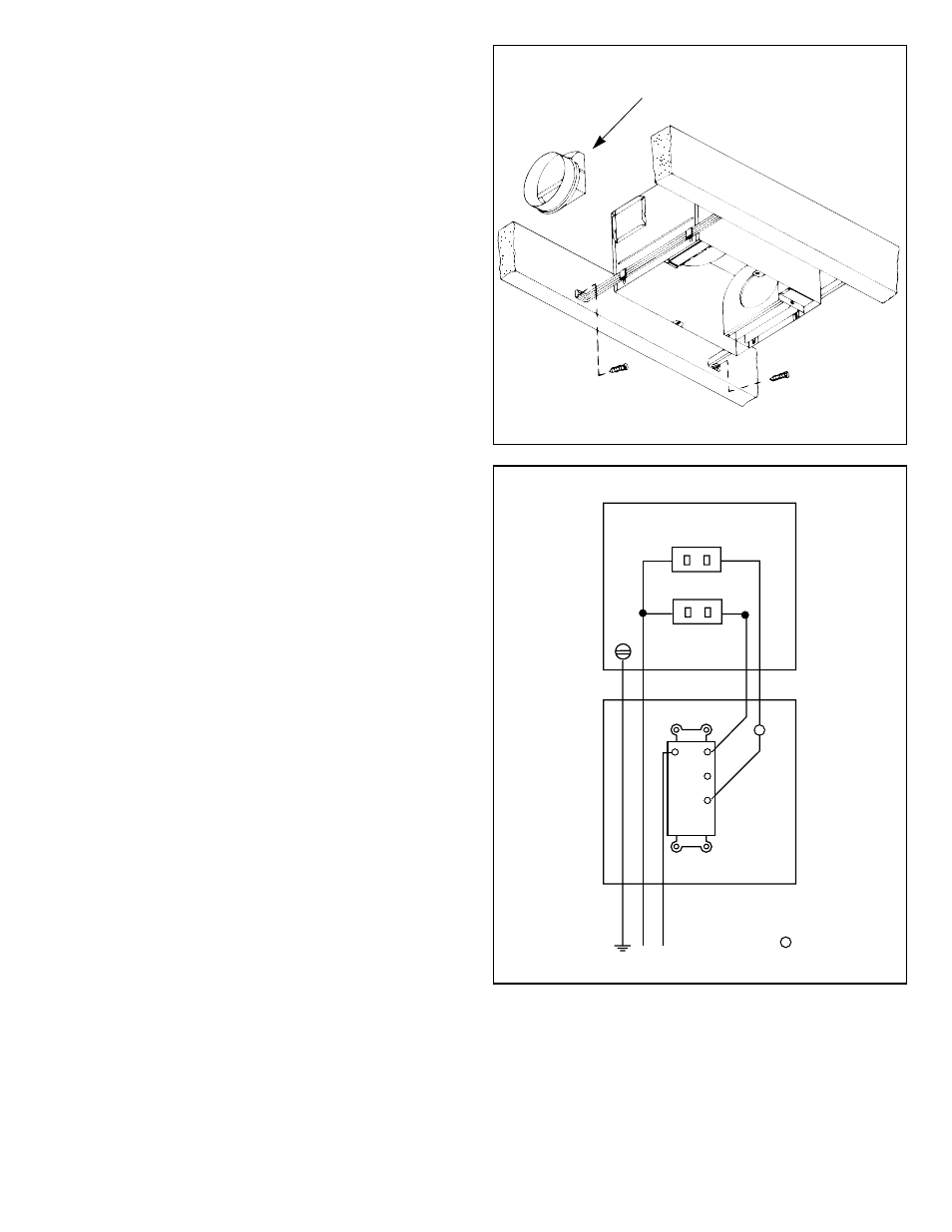
MOUNTING THE HOUSING
1. Locate housing between joists.
2. Refer to Figure 5. Using nails, secure hanger bars to joists.
NOTE: The hanger bar brackets are adjustable.
Allowing for the thickness of the finished ceiling,
mount hanger bars so that edge of housing will be
flush with the finished ceiling.
3. Adjust brackets as required. Tighten brackets.
INSTALLING THE DUCTWORK
1. Refer to Figure 5. Install duct collar.
2. Using 4" round duct, connect duct to collar and tape
connection.
INSTALLING THE SWITCH
1. Install double-gang switch box in chosen location.
2. Refer to Figure 6. Run wiring and make wiring
connections.
3. Use supplied screws to secure switch bracket assembly
to switch box.
4. Using supplied screws, secure wall plate to switch bracket.
INSTALLING AND CONNECTING THE WIRING
Refer to Figure 6.
All wiring must comply with local codes and unit must
be properly grounded.
1. Using 12-gauge wire, run 120vAC, 60 Hz wiring (with
ground) from a power source to the wall switch location.
The unit must be wired on a separate 20 Amp circuit.
2. Run wiring from switch location to housing as shown in the
wiring diagram.
3. Make wiring connections as shown in wiring diagram.
4. Replace junction box cover. Slide slotted hole in cover over
screw. Tighten screw securely.
5. Secure wire cover with one screw.
6. Insert heater and ventilator plugs into proper receptacles
as shown.
MOUNTING THE GRILLE ASSEMBLY
1. Refer to Figure 7. Using two screws (provided), secure
grille to housing.
FIGURE 5
FIGURE 6
DUCT COLLAR
HEAT
VENT
HEATER
JUNCTION BOX
HEATER
(WHITE)
RED
WHT
BLU.
WHT
VENT
SWITCH
BOX
120vAC
LINE
GROUND
WHITE
BLACK
T
NOTE:
WHEN THERMOSTAT
OR TIMER IS USED,
CONNECT AT
T