Zanussi ZES 3921 IBA User Manual
Page 20
Electrical connection
• Ground the appliance according to safety
precautions.
• Make sure that the rated voltage and type of
power on the rating plate agree with the volt-
age and the power of the local power supply.
• This appliance is supplied with a mains ca-
ble. It has to be supplied with a correct plug,
able to support the load marked on the rating
plate. The plug has to be fitted in a correct
socket.
• Any electrical component must be installed
or replaced by the Service Force Centre
technician or qualified service personnel.
• Always use a correctly installed shockproof
socket.
• Make sure that there is an access to the
mains plug after installation.
• Do not pull the mains cable to disconnect
the appliance. Always pull the mains plug.
• The appliance must not be connected with
an extension cable, an adapter or a multiple
connection (risk of fire). Check that the
ground connection is in conformity with the
standard and regulations force.
• The power cable must be placed in such a
way that it does not touch any hot part.
• Connect the appliance to the mains with a
device that lets to disconnect the appliance
from the mains at all poles with a contact
opening width of minimum 3 mm, eg. auto-
matic line protecting cut-out, earth leakage
trips or fuse.
• None of a parts of the connection cable can
not get a temperature 90 °C. The blue neu-
tral cable must be connected to the terminal
block label with "N". The brown (or black)
phase cable (fitted in the terminal block con-
tact marked with "L") must always be con-
nected to the live phase.
Replacement of the connection cable
To replace the connection cable use only
H05V2V2-F T90 or equivalent type. Make sure
that the cable section is applicable to the volt-
age and the working temperature. The yellow/
green earth wire must be approximately 2 cm
longer than the brown (or black) phase wire.
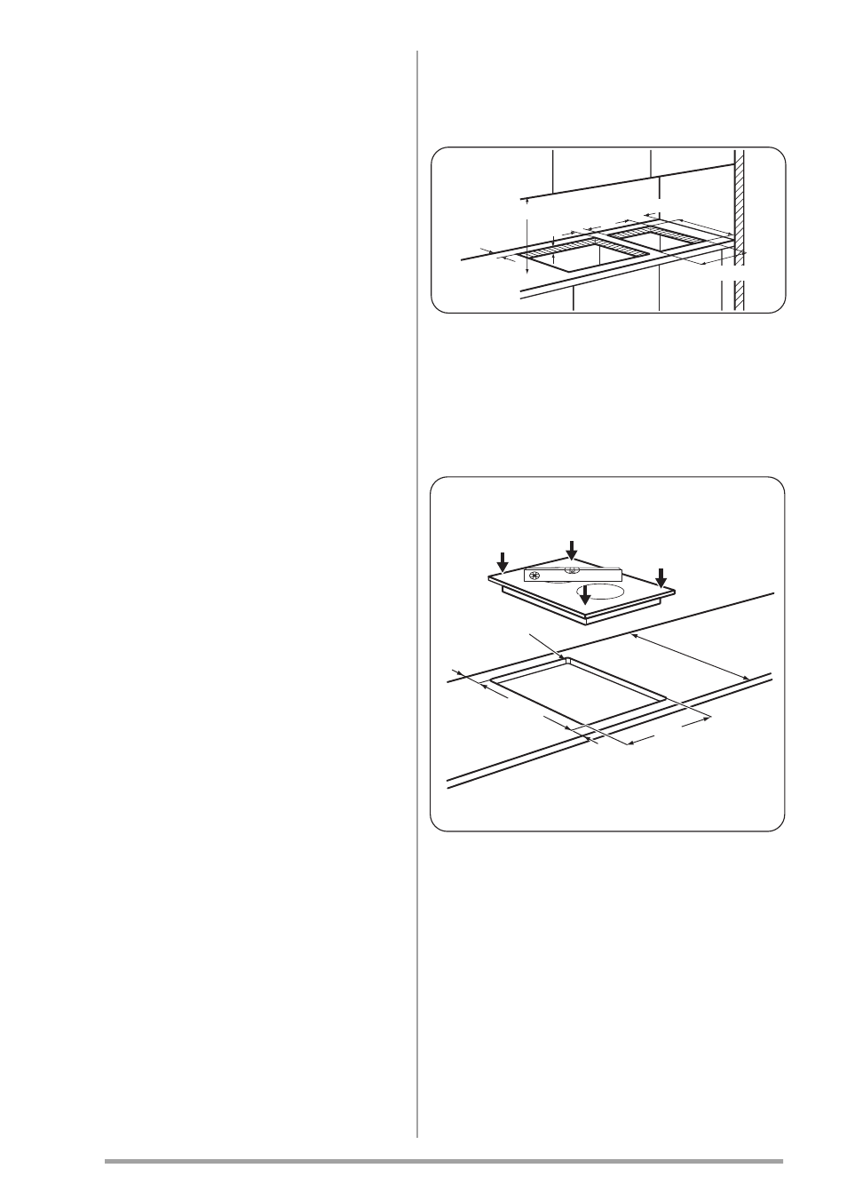
Assembly
40-50 mm
55 mm
30 mm
min. 650 mm
490 mm
min. 100 mm
270 mm
If several 30 cm hobs are to be installed side by
side into the same cut out, an assembly kit in-
cluding a support side bracket and supplemen-
tary seals is available at our Service Centres.
The relevant installation instructions are sup-
plied within the kit package.
=
=
270
+1mm
600
mm
R 5
mm
490
+1mm
20
www.zanussi.com