Finishing, Operation, Maintenance – Napoleon Fireplaces EF31H User Manual
Page 5: Flame effect
5
W415-0469 / A / 01.04.05
Sides................. 0 mm / 0 inches
Sides................. 0 mm / 0 inches
Floor................. 0 mm / 0 inches
Top
0 mm / 0 inches
The minimum distance from the top of the unit that the
mantel can be installed is 0", at any depth.
When using paint or lacquer to finish the
When using paint or lacquer to finish the
When using paint or lacquer to finish the
When using paint or lacquer to finish the
When using paint or lacquer to finish the
mantel, such paint or lacquer must be heat
mantel, such paint or lacquer must be heat
mantel, such paint or lacquer must be heat
mantel, such paint or lacquer must be heat
mantel, such paint or lacquer must be heat
resistant to prevent discolouration.
resistant to prevent discolouration.
resistant to prevent discolouration.
resistant to prevent discolouration.
resistant to prevent discolouration.
Sides......................... 0 inches
Back.......................... 0 inches
Floor..........................0 inches
Top............................ 0 inches
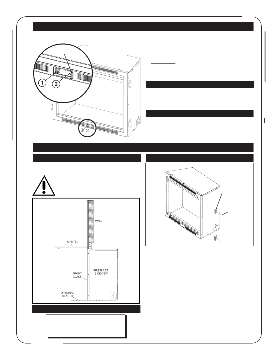
1. Choose fireplace location.
2. Place fireplace in position.
3. Frame in fireplace with header across the top. It is im-
portant to allow for the finished facing materials when set-
ting the depth of the unit.
4. Remove the two screws from the sides of the fireplace
and attach the nailing tabs with the screws.
5. To determine the final location of the nailing tab, you
must first determine the thickness of your finishing mate-
rial (i.e. sheetrock/drywall) This will determine the dimen-
sion from the front edge to the nailing tab. Secure with a
sheet metal screw supplied.
6. Attach the nailing tabs to the frame.
MANTEL
FRAMING AND FINISHING
CLEARANCE TO COMBUSTIBLES
Nailing
Tab
Installation
FINISHING
Sheet
Metal
Screw
Bulb Replacement : If the flame appears darker on one
side of the fireplace, check the light bulbs to ensure that
one has not burned out.
Bulb must be replaced with a MAX 75 watt Quartz 78mm
light bulb. See Light Replacement section.
OPERATION
MAINTENANCE
The flame generator has a random modulating control
which causes the flame effect to speed up and slow down
sporadically. This action creates the realistic flame appear-
ance and can not be modified.
FLAME EFFECT
1.
1.
1.
1.
1. Heater
Heater
Heater
Heater
Heater
To set the heater at the maximum setting - roll the switch
up to the uppermost setting.
To turn the heater off - roll the switch down to the lower
most setting.
2.
2.
2.
2.
2. Flame effect
Flame effect
Flame effect
Flame effect
Flame effect
The rocker switch is used to turn the flame effect on and
off. Depress the left side of the switch to turn the flame
effect on and the right side to turn off.
There are two operation controls for the EF31.
There are two operation controls for the EF31.
There are two operation controls for the EF31.
There are two operation controls for the EF31.
There are two operation controls for the EF31.
1 - Controls the heater.
2 - Controls the flame effect.
T
T
T
T
To access the contr
o access the contr
o access the contr
o access the contr
o access the controls
ols
ols
ols
ols,,,,,
slide the control door to
slide the control door to
slide the control door to
slide the control door to
slide the control door to
the right.
the right.
the right.
the right.
the right.
Control Door
Control Door
Control Door
Control Door
Control Door