Fuse replacement procedure, Maintenance – Thetford Norcold 9183 User Manual
Page 12
Fuse Replacement Procedure
The refrigerator’s electrical circuits are fused to protect them from a circuit overload. If the "Diagnostic Codes and Their
Meaning" section indicates that the refrigerator fuse is blown, follow the replacement procedures below.
1. Turn the refrigerator to "OFF".
2. Disconnect the AC power cord from the
wall receptacle.
3. Disconnect the AC power cord from the
power board cover at the rear of the refrigerator
from the power board cover.
4. Disconnect the 12 volt DC supply wires from
the power board cover (A).
5. Remove the ignition wire/sense wire from the
power board cover.
6. Remove the three screws which secure the
power board cover to the refrigerator, pull
cover away. Do not operate refrigerator
without power board cover.
7. For 3-Way models, disconnect the supply
wires from the extention board (B) as shown
in Figure 8.
Note! Remember how the wires were removed.
Reattach wires to the same location as they
were when removed.
1. Blue wire from power board connects to termi-
nal #7 of extention board.
2. Red wire from power board connects to termi-
nal #9 of extention board.
3. Black wire connected to refrigerator chassis
connects to terminal #8 of extention board.
4. Yellow wire of the DC heater connects to termi-
nal #6 of the extention board.
8. Remove the two screws which secures the ex-
tention board cover (B) to the refrigerator. Pull
cover away from the refrigerator. Do not operate refrigerator without cover.
9.. Replace blown fuse with the specified fuse listed in the WARNING above.
10. If a fuse continues to blow, contact your dealer or a Norcold Service Center for corrective action.
4
Maintenance
CAUTION . Failure to follow this procedure can lead to personal injury or property damage.
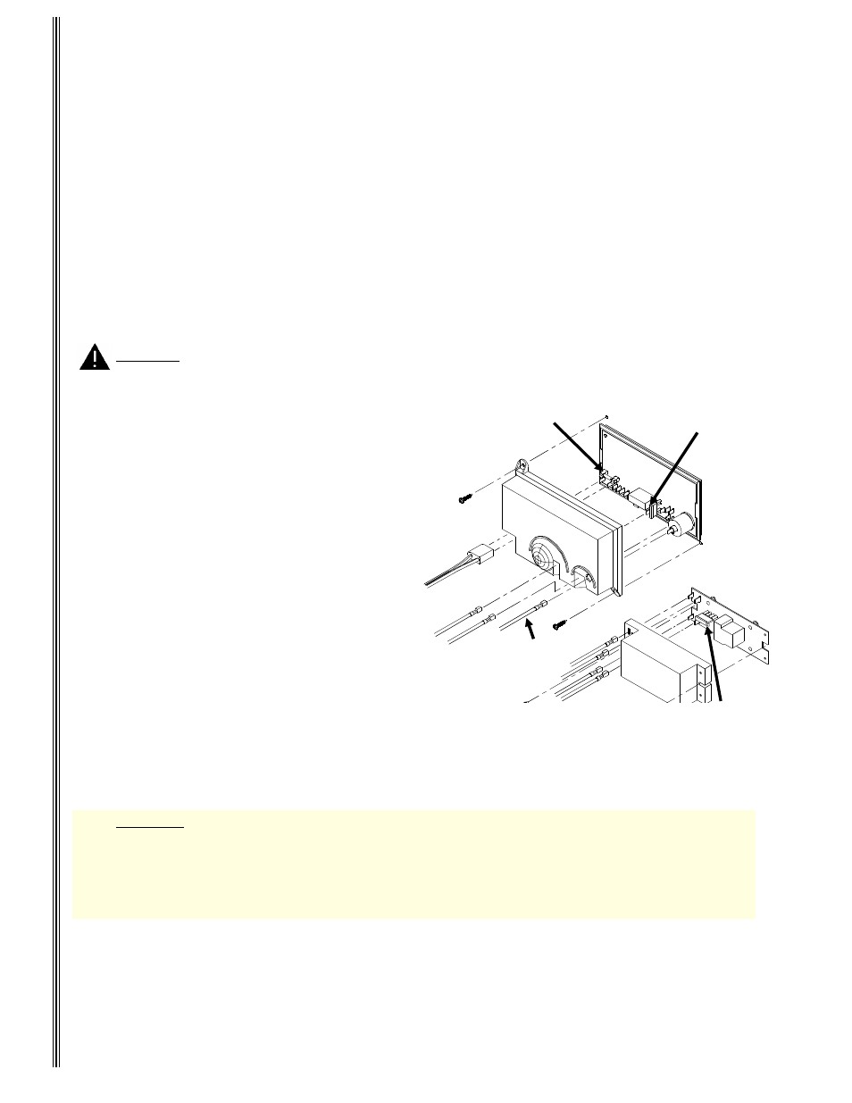
Figure 8
AC Supply
Cord
Mounting Screw
12 VDC Supply
Wires
Ignition/Sense
Wire
5 Amp Glass Cartridge
AC Fuse
20 Amp Blade-Type
Fuse (3-Way
Models Only)
3 Amp Blade-Type Fuse
(Control Fuse)
+
Grd.
1
2
3
WARNING A circuit overload can result in an electrical fire when incorrectly sized fuses are used.
To prevent a possible electrical fire, follow the fuse specifications given below:
DC Control Circuit - 3 amp (purple) blade-type automotive
DC Heater Circuit - 20 amp (yellow) blade-type automotive
AC Circuit - 5 amp glass cartridge
1
2