B-vent specifics - model gs28, Adapter installation – Napoleon Fireplaces GS 28-N User Manual
Page 11
11
W415-0153 / A / 10.29.01
COMBUSTION AIR COVER
PLATES & GASKETS
INST
INST
INST
INST
INSTALLING 'B'
ALLING 'B'
ALLING 'B'
ALLING 'B'
ALLING 'B' VENT
VENT
VENT
VENT
VENT:::::
Follow the instructions for "Wall and Ceiling Protection".
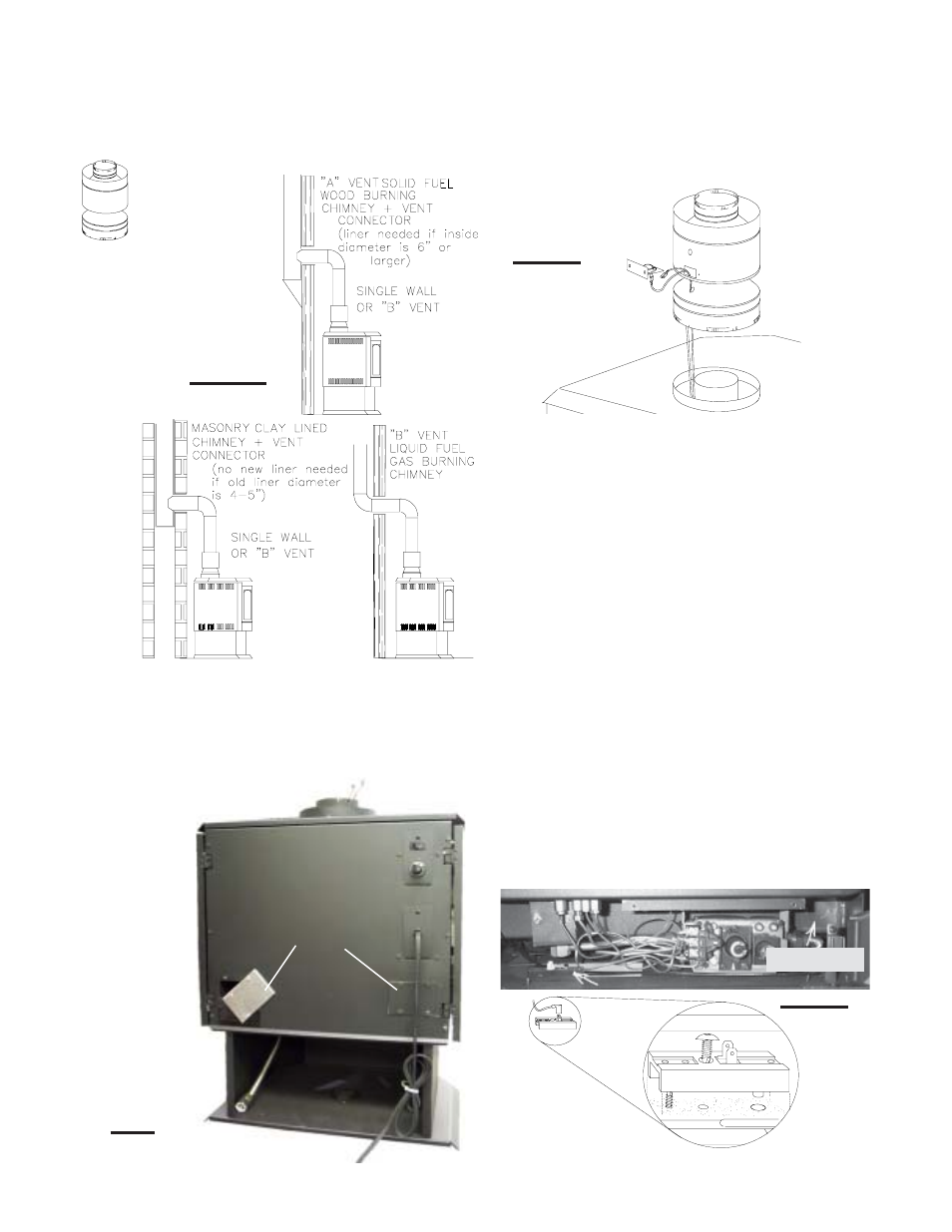
ADAPTER INSTALLATION
FIGURE 24
1. Remove the spill switch bracket from the rear of the
adapter.
2. Gently pull the two wire terminals (located inside the 7"
flue collar at the top of the stove) out approximately 8 inches.
3. Bring the wires through the lower hole in the adapter and
out the spill switch opening.
To pass the wires through
the hole more easily, temporarily tape the two terminals
together.
4. With the spill switch opening aligned to the back of the
stove, push the crimped edge of the adapter into the stove
flue collar.
5. Connect the wire terminals to the spill switch and re-
secure the bracket.
6. Secure the terminal block into place as shown with the
screw supplied.
7. Unscrew the wire access cover plate from the rear right
hand side of the firebox. Remove and discard the gasket.
SEE FIGURE 25. Remove the knockout from the cover plate
and insert the protective bushing. Pull both spill switch wires
through the bushing taking up any slack. Replace the cover
plate. Connect one wire end to the terminal block and the
other end to terminal 1 of the gas valve. FIGURE 31. Con-
nect the two wires running down the left side of the unit
from the on-off switch to the remaining tab on the terminal
block and to terminal 3 on the gas valve.
CHIMNEY INSTALLATION
THREE TYPES OF
CHIMNEY SYSTEMS
MAY BE USED WITH
THIS STOVE:
B-VENT SPECIFICS - MODEL GS28
FIGURES 22
SWITCH
SPILL
ADAPTER
FIGURE 24
'B' VENT ADAPTATIONS
1. Remove and discard the two combustion air cover plates
and gaskets located on the rear panel of the unit. SEE FIG-
URE 23.
2. Replace the four screws per side to secure the rear
panel to the unit.
FIG. 23
FIGURE 25
TERMINAL BLOCK
TERMINAL BLOCK
WIRE ACCESS
WIRE ACCESS
WIRE ACCESS
WIRE ACCESS
WIRE ACCESS
CO
CO
CO
CO
COVER PLA
VER PLA
VER PLA
VER PLA
VER PLATE
TE
TE
TE
TE