Nailing tab installation, Ab c, Minimum mantle and enclosure clearances – Napoleon Fireplaces BGNV36N User Manual
Page 7: Figure 12 a-c, Figure 13 b&c
7
W415-0275 /D / 10.01.07
1”
12”
4
5
/
8
”
1”
4” B-VENT
FIRESTOP
3”
FIGURE 13 a
NAILING
TAB
FIGURE 11
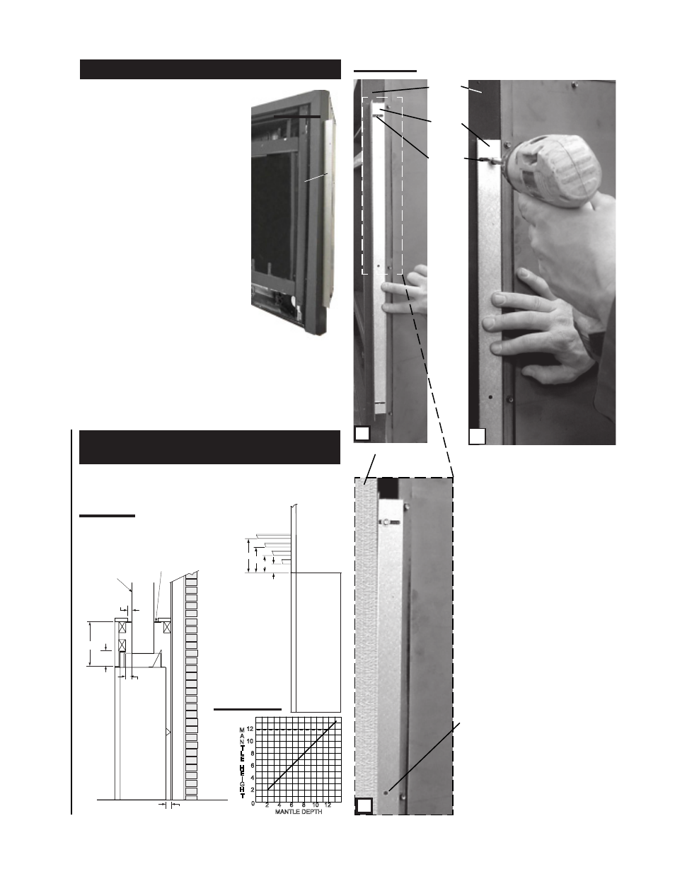
1) Attach the nailing tabs to the corner posts using
the 2 sheet metal screws supplied. Se-
cure through the centre of the top and
bottom slots in the nailing tab and then
through the existing holes in the cor-
ner posts.
If there are no existing holes, follow
these instructions:
Position the nailing tab so that the front
face is offset with the front edge of the
corner post (approx. ½"). Centre the
nailing tab vertically on the corner
post.
Figure 12 a.
Drill through the centre of the top and
bottom slots in the nailing tab. Secure
using the two sheet metal screws
supplied. This allows the nailing tab
to slide back and forth for desired fram-
ing. Figure 12 b.
2) To determine the final location of the nailing tab
you must first determine the thickness of your finishing
material (i.e. drywall). This will determine the dimension
from the front edge of the corner post to the nailing tab.
Once the nailing tab is in the desired location, drill through
the centre hole of the nailing tab. Secure with a sheet metal
screw*. Figure 12 c.
* Additional set screws may be installed.
NAILING TAB INSTALLATION
TOP
SLOT
FINISHING
MATERIAL
CORNER
POST
NAILING
TAB
A
B
C
CENTRE
HOLE
FIGURE 12 a-c
MINIMUM MANTLE AND
ENCLOSURE CLEARANCES
Combustible mantle clearance can vary according to the
mantle depth. Use the graph to help evaluate the clear-
ance needed.
MANTLE DEPTH
H
T
H
I
G
E
N
L
E
T
M
A
6
6
2
0
4
2
4
10
8
12
12
8 10
TOP OF
FIREPLACE
8” MANTLE
6”
4”
2”
2”
4”
6”
8”
FIGURE 13 b&c