Novatel SMART-AG User Manual
Page 2
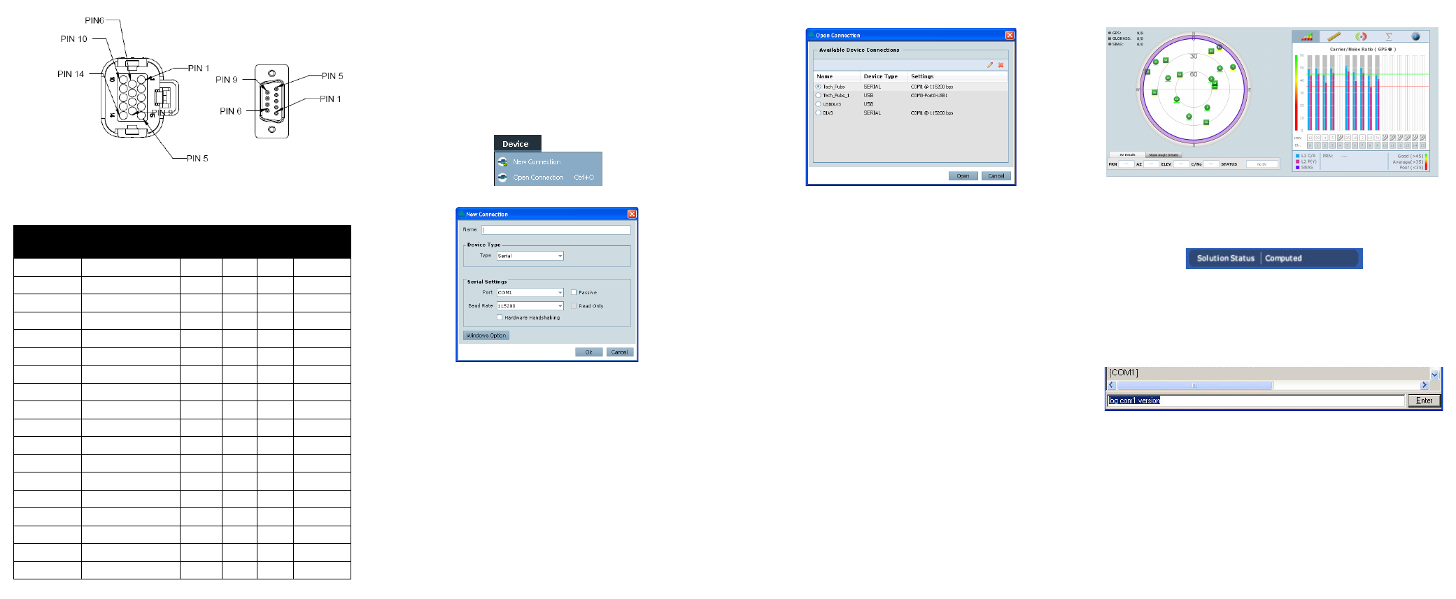
Figure 1: 14-pin and DB-9 Pin Numbers
ESTABLISHING RECEIVER COMMUNICATION
To open a serial port to communicate with the receiver, complete
the following steps.
1. Launch Connect from the Start menu folder specified during
the installation process. The default location is Start |
All Programs | NovAtel PC Software | NovAtel Connect.
2. Select New from the Device Menu.
3. Enter a name for the Connection setup.
4. Select Serial from the Type list.
5. Select the computer port to which the SMART-AG is
connected, from the Port list.
6. Set the COM port for the receiver to communicate through.
7. Select 115200 from the Baud Rate list.
8. Ensure the Hardware Handshaking box is not checked and
click the OK button.
9. From the Device menu select Open Connection.
10. Select the Open button to open SMART-AG
communications.
Connect establishes the communication session with the
receiver and displays the progress. Once connected, the
progress box disappears and several windows open, including
the Console window. Connect is now ready for use to view status
information, enter commands or log data.
USING NOVATEL CONNECT
Connect provides access to key information about your receiver
and its position. The information is displayed in windows
accessed from the View menu. For example, select Position
Window from the View menu to display the position solution of
the receiver. To show details of the GNSS and geostationary
(SBAS) satellites being tracked, select the a Tracking Status
Window from the View menu. Select Help from the main menu
for more details on Connect, its windows and features.
DETERMINING WHEN THE POSITION IS VALID
When the receiver has a valid position, the Solution Status field
in Connect’s Position window shows Computed.
ENTERING COMMANDS
The SMART-AG uses a comprehensive command interface.
Commands can be sent to the receiver using the Console
window in Connect, which is opened from the View menu. Enter
commands in the text box at the bottom of the Console window.
The OEMV Family Quick Reference Guide, provided on the CD
and available on the NovAtel website, provides comprehensive
information about available commands. The SMART-AG User
Manual provides information on a subset of these commands; in
particular, the ones commonly used on the SMART-AG.
Table 2: SMART-AG Cable Wire Colors
Wire Color
Signal Name
14-pin
(J1)
DB-9
(J2)
DB-9
(J3)
Label
Red
COM1_TXD
1
2
White
COM1_RXD
2
3
Red
COM2_TXD
3
2
White COM2_RXD
4
3
Black
COM1 GND
5
5
Black
COM2 GND
5
5
White-Black MKI GND
5
MKI GND
White-Black ER GND
5
ER GND
White-Black PPS GND
5
PPS GND
Yellow
CANI+
6
CANI+
Green
CANI-
7
CANI-
-
NO CONNECT
8
Black
PWR RET (GND)
9
BATT-
Blue
EMD RADAR OUT 10
ER_OUT
White MAN
MARK
IN
11
MKI
Orange
PPS
12
PPS
-
NO CONNECT
13
Red
PWR INPUT
14
BATT+