Porter-Cable N066288 User Manual
Page 7
7
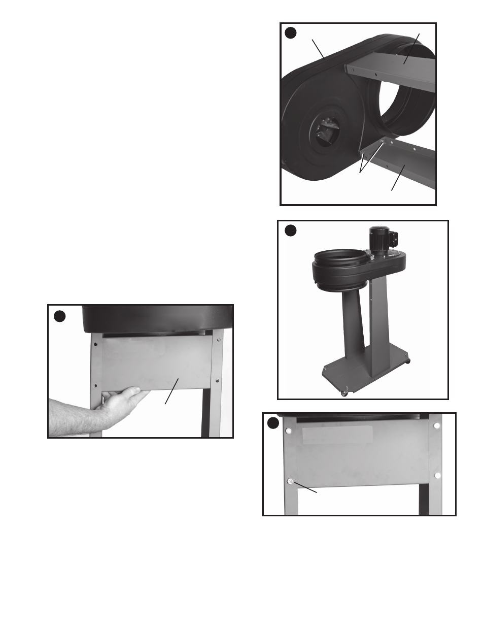
ATTACHINg MOTOR AND BLOWER ASSEMBLY
TO FRAME
1. Place motor assembly and base assembly on their side.
2. Align the four holes, two shown at (C), on the top of the
side supports (A) Fig. 7, with the four holes in the motor
assembly (B).
3. Place a 5/16" lockwasher onto a 5/16-18 x 5/8" hex head
screw and insert the bolt thru the side support and thread
bolt into the tapped hole in the motor assembly and
tighten securely.
4. Repeat this process for the three remaining holes.
5. Fig. 8 shows the motor and blower assembly attached to
the side supports.
SUPPORT
1. Place the support (A) Fig. 9 inside the two side supports
NOTE: MAKE SURE SUPPORT (A) IS ATTACHED TO THE
SIDE SUPPORTS CLOSEST TO THE MOTOR.
2. Align the four holes in the support with the four holes in
the side supports as shown in Fig. 9.
3. Insert a 5/16-18 x 5/8" hex head screw (B) Fig. 10, thru the
side supports and the support.
4. Place a 5/16" lockwasher on the hex head screw.
5. Thread a 5/16-18 hex nut on the hex head screw and
tighten securely.
6. Repeat this process for the three remaining holes for
attaching the support.
7. Fig. 10 shows the support attached to the side supports.
C
A
A
B
7
8
9
A
B
10