Anchor clamp(s) installation, continued, Water connections – Pentair ThermalFlo User Manual
Page 15
7
ThermalFlo Installation and User’s Guide
HEAT PUMP
ANCHOR CLAMP
AIR COIL GUARD
AIR
COIL
BOLT ANCHOR
(installer provided)
HEAT PUMP
BASE
1-3/8" HEX BOLT
(installer provided)
CONCRETE
EQUIPMENT PAD
Figure 5.
POOL HEATER
CHEMICAL LOOP
2 LB.
CHEMICAL RESISTANT
CHECK VALVE
CHEMICAL FEEDER
TO POOL OR SPA
POOL PUMP
FROM POOL OR SPA
MANUAL BYPASS VALVE
FILTER
Figure 6. Standard Plumbing Layout
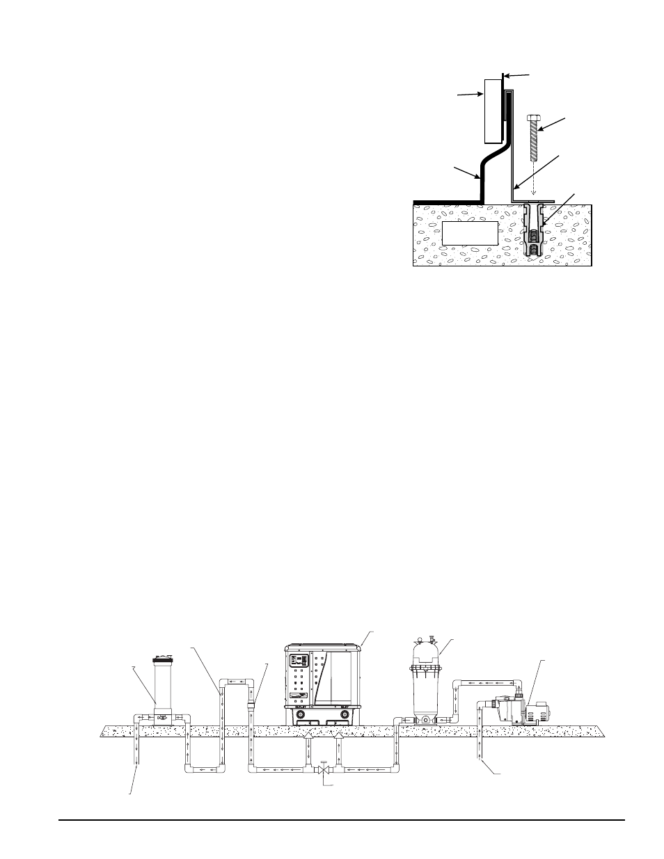
Anchor Clamp(s) Installation, continued
6. Drill a hole in the cement using a masonry drill bit, with a
diameter as determined by the concrete anchor, at each of the
marks on the equipment pad. The hole should be approximately
1½ in. deep.
7. Insert a bolt anchor into each of the holes. Be sure the anchors
are set completely into the holes
8. Position the anchor clamps so that the holes in the clamps are
over the bolt anchors. Be sure that the clamp hooks are over the
lip of the heat pump base, see Figure 5.
9. Insert an anchor bolt through each clamp into the anchor and
tighten to secure the clamp and heat pump to the equipment pad.
Water Connections
Plumbing layout
See Figure 6, illustrating the standard plumbing layout with a single heat pump unit. Following the diagram from
right to left, the plumbing sequence is as follows:
Pool > Skimmer and Main Drain > Pool Pump > Filter > Heat Pump > Check Valve > Chemical Loop > Chlorinator > Pool
NOTE: For normal installations, do not install a shut-off valve or any kind of variable restriction in
the water piping between the heat pump outlet and the pool/spa.
The heat pump must be protected from back-siphoning of water. If there is any chance of back-siphoning,
provide a check valve between the pool and the heat
pump outlet. Arrangement of pool system components
other than as illustrated in Figure 6. and the following diagrams can affect the operation of the heat pump’s
water pressure switch. Location of the heat pump above or below the pool water surface can also affect
operation of the switch. In general, the pressure switch can be adjusted to accommodate this effect if the heat
pump water connections are no more than six (6) feet below the pool water surface or no more than fifteen 15
feet above it. See instructions for pressure switch adjustment (
page 20
) in the heat pump start-up section of this
manual for more information. If the heat pump is installed outside of this range, an external pressure switch may
need to be installed in the plumbing upstream of the heat pump. Call the Pentair Water Heat Pump Technical
Service department at (800) 831-7133 for details.
Be advised that when pool equipment is located below the pool surface a leak can result in large-scale water
loss or flooding. Pentair cannot be responsible for such water loss or flooding or the damage caused by either
occurrence.