Service and adjustments – Poulan XT 96016002200 User Manual
Page 19
19
TO REPLACE MOTION DRIVE BELT(See Fig. 20)
Park the tractor on level surface. En gage parking brake.
For as sis tance, there is a belt installation guide decal on
bottom side of left footrest.
BELT REMOVAL -
• Remove mower (See “TO RE MOVE MOWER” in this
section of manual).
NOTE: Observe entire motion drive belt and position of all
belt guides and keepers.
• Remove belt from stationary idler and clutching idler.
• Remove belt downward from around en gine pulley.
• Pull belt slack toward rear of trac tor. Remove belt up-
wards from transaxle pulley by de flect ing belt keep ers.
• Remove belt from center span keeper and pull belt
away from tractor.
BELT INSTALLATION -
• Carefully work new belt down be tween transaxle belt
keepers and onto the input pulley.
• Slide belt into the center span keeper.
• Pull belt toward front of tractor and roll around the top
groove of engine pulley.
• Install belt through stationary idler and clutch ing idler.
• Make sure belt is in all pulley grooves and in side all
belt guides and keep ers.
• Install mower (See “TO IN STALL MOWER” in this
sec tion of manual).
FIG. 20
TRANSAXLE
PULLEY
STA TION ARY
IDLER
CLUTCHING
IDLER
ENGINE PULLEY
CENTER SPAN
KEEPER
FIG. 21
TO ADJUST STEERING WHEEL ALIGNMENT
If steering wheel crossbars are not horizontal (left to right)
when wheels are positioned straight forward, remove steer-
ing wheel and reassemble per instructions in the Assembly
section of this manual.
FRONT WHEEL TOE-IN/CAMBER
The front wheel toe-in and camber are not adjustable on
your tractor. If damage has occurred to affect the front
wheel toe-in or camber, contact your nearest authorized
service center/department.
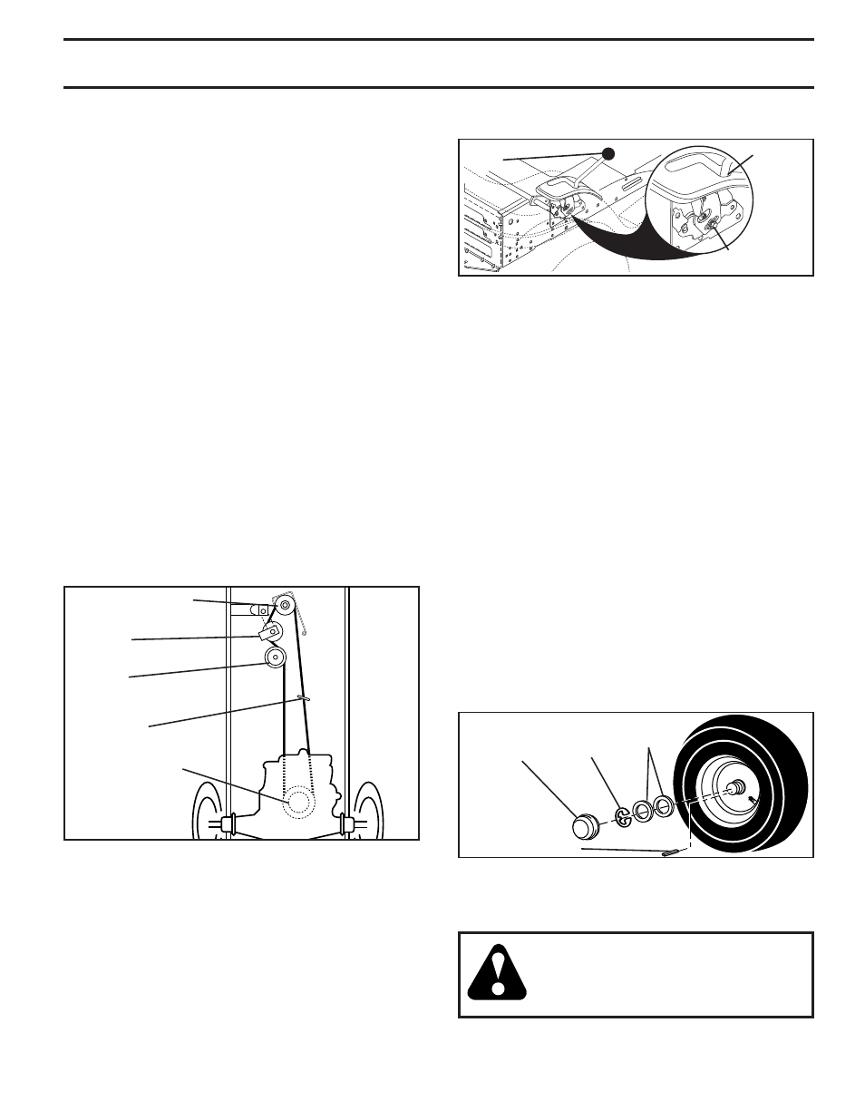
FIG. 22
TO REMOVE WHEEL (See Fig. 22)
• Block up axle securely.
•
Remove axle cover, retaining ring and washers to allow
wheel removal (rear wheel contains a square key - Do
not lose).
• Repair tire and reassemble.
• On rear wheels only: align grooves in rear wheel hub
and axle. Insert square key.
• Replace washers and snap retaining ring securely in
axle groove.
• Replace axle cover.
NOTE: To seal tire punctures and prevent flat tires due to slow
leaks, tire sealant may be purchased from your local parts
dealer. Tire sealant also prevents tire dry rot and corrosion.
RE TAIN ING
RING
WASH ERS
SQUARE KEY
(REAR WHEEL ONLY)
AXLE
COVER
TO START ENGINE WITH A WEAK BATTERY
(See Fig. 23)
WARNING: Lead-acid batteries gen er ate
ex plo sive gases. Keep sparks, flame and
smoking ma te ri als away from bat ter ies.
Always wear eye pro tec tion when around
batteries.
If your battery is too weak to start the engine, it should be
recharged. (See "BATTERY" in the Maintenance sec tion
of this man u al).
SERVICE AND ADJUSTMENTS
TRANSAXLE GEAR SHIFT LEVER NEU TRAL
ADJUSTMENT (See Fig. 21)
The transaxle should be in neutral when the gear shift lever is
in neutral (lock gate) position. The adjustment is preset at the
factory; however, if adjustment is needed, proceed as follows:
• Make sure transaxle is in neutral.
NOTE: When the tractor rear wheels move freely, the
transaxle is in neutral.
•
Loosen adjustment bolt in front of the right rear wheel.
• Position the gear shift lever in the neutral position.
• Tighten adjustment bolt securely.
GEARSHIFT
LEVER
ADJUSTMENT
BOLT
NEUTRAL
LOCK
GATE
NOTE: If additional clearance is needed to get to ad just ment
bolt, move mower deck height to the lowest position.
2. Place gear shift lever in neutral (N) position.
The rear wheels must lock and skid when you try to manually
push the tractor forward. If the rear wheels rotate, then the
brake needs to be serviced. Contact a qualified service center.