Warning – Poulan Pro PP46ET User Manual
Page 17
17
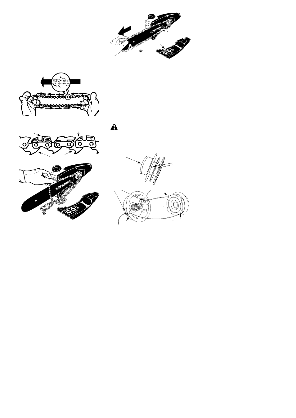
TO REPLACE CHAIN:
1. Move ON/OFF switch to the OFF position
and disconnect spark plug.
2. Remove bar clamp nut.
3. Remove bar clamp.
4. Turn adjusting screw by hand counter-
clockwise until adjusting pin just touches
the stop.
5. Slide guide bar behind sprocket until
guide bar stops against sprocket.
6. Remove the old chain.
7. Carefully remove new chain from pack-
age. Hold chain with the drive links as
shown.
CUTTERS MUST FACE IN
DIRECTION OF ROTATION
Tip of
Bar
Cutter
Drivelink
Cutters
Depth Gauge
Drive Links
8. Place chain over sprocket, fitting the
drive links in the sprocket.
9. Fit bottom of drive links between the teeth
in the sprocket in the nose of the guide
bar.
10. Fit chain drive links into bar groove.
11. Pull guide bar forward until chain is snug
in guide bar groove. Ensure all drive links
are in the bar groove.
12. Now, install bar clamp making sure the
adjusting pin is positioned in the lower
hole in the guide bar.
Adjusting Pin
Lower
Hole
Guide Bar
13. Install bar clamp nut and finger tighten
only. Do not tighten any further at this
point. Proceed to the CHAIN ADJUST-
MENT section.
CHAIN ADJUSTMENT
See CHECK CHAIN TENSION in MAINTE-
NANCE section.
REPLACING THE LINE
1. Remove spool by firmly pulling on tap
button.
2. Clean entire surface of hub and spool.
3. Replace with a pre-wound spool, or cut two
lengths of 12-1/2 feet of 0.080″ (2 mm) di-
ameter Poulan PRO brand line.
WARNING:
Never use wire, rope,
string, etc., which can break off and become a
dangerous missile.
4. Insert ends of the lines about 1/2 inch (1
cm) into the small holes on the inside of
spool.
Small
Holes
Spool
Hub
Line in Notch
Line in Notch
Line exit holes
5. Wind the line evenly and tightly onto the
spool. Wind in the direction of the arrows
found on the spool.
6. Push the lines into the notches, leaving 3
to 5 inches (7 -- 12 cm) unwound.
7. Insert the lines into the the exit holes in
the hub as shown in the illustration.
8. Align the notches with the line exit holes.
9. Push spool into hub until it snaps into place.
10. Pull the lines extending outside of the hub
to release the lines from the notches.