Peavey ENVOY 110 User Manual
Page 4
LOW, MID, and HIGH
CLEAN CHANNEL (5)
Passive tone controls that regulate the low, mid, and high frequencies of the Clean channel.
PRE GAIN (6)
Controls the input gain of the Lead channel.
THRASH SWITCH (7)
Notches the mid range about 20
GAIN SWITCH (8)
Boosts the overall system gain. Depress to the “in” position to activate.
LOW, MID, and HIGH
LEAD CHANNEL (9)
Passive tone controls that regulate the low, mid, and high frequencies of the Lead channel.
POST GAIN
Controls the overall volume level of the lead channel. The final level adjustment should be made after the
desired sound has been achieved.
REVERB LEVEL (11)
Controls the overall reverb level.
POWER LED (12)
Illuminates when AC power is being supplied to the amp.
POWER SWITCH (13)
Depress the switch to the “on” position. The red LED will illuminate indicating power is being supplied to the
unit.
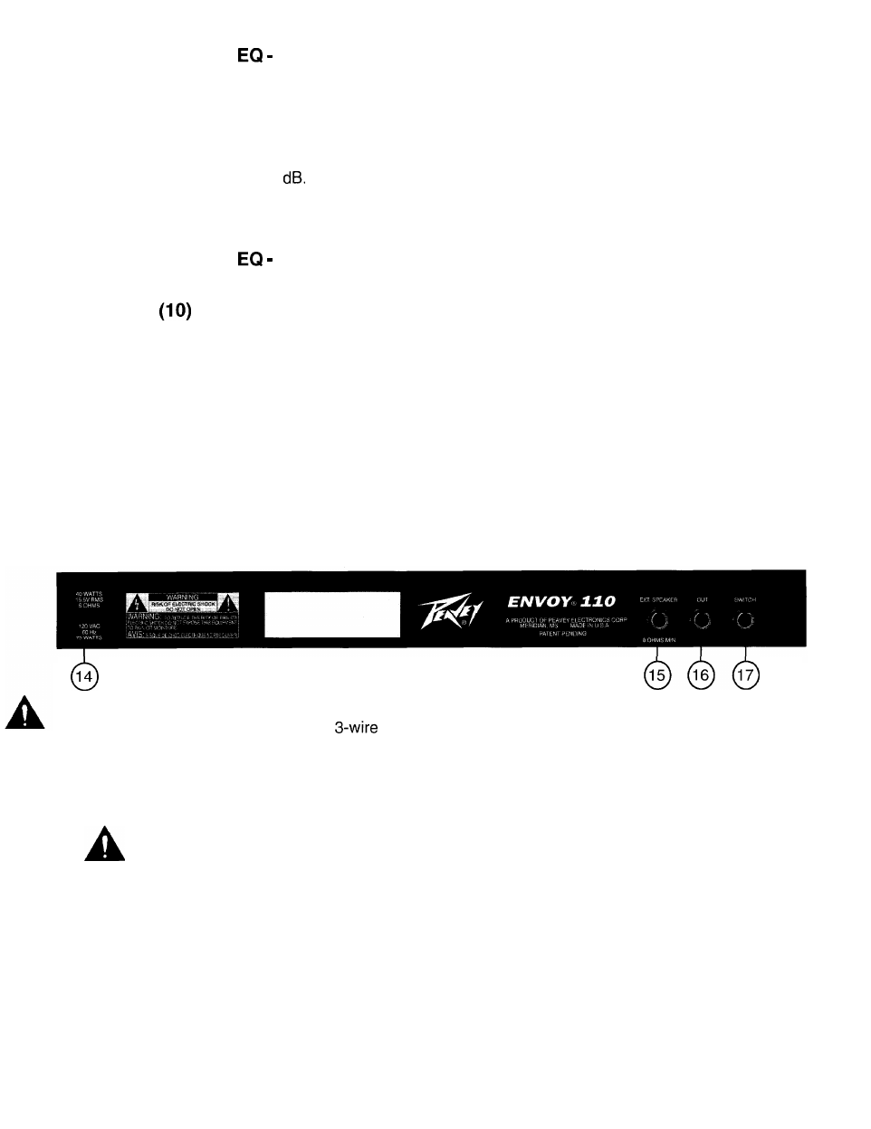
Back Panel:
14
LINE CORD (120 V products only) (14)
For your safety, we have incorporated a
line (mains) cable with proper grounding facilities. It is not
advisable to remove the ground pin under any circumstances. If it is necessary to use the equipment without
proper grounding facilities, suitable grounding adaptors should be used. Less noise and greatly reduced
shock hazard exists when the unit is operated with the proper grounded receptacles
EXTERNAL SPEAKER JACK (15)
Provided for connection of external speaker cabinet. Minimum total impedance is 8 ohms.
Disconnects internal speaker when used.
PREAMP OUT (16)
The preamp output can be used to route the amplified signal to a mixing console, tape recorder, etc. Con-
nect the preamp output using a shielded cable to an input of the tape recorder, mixer, etc. This patch does
not affect the operation of the amplifier.
REMOTE SWITCH JACK (17)
Provided for the connection of the optional remote footswitch. The footswitch is used to select the Lead or
Clean channel and defeat Reverb. When using remote footswitch, always insert plug fully (second click) to
insure proper operation.
NOTE: The Channel Select switch must be in the “in” position in order for the footswitch to function properly.
4