Pool heater wiring connection diagram, Jmp 1 jmp 1, Connection diagram – Pentair 250K BTU/HR User Manual
Page 36: 12 position receptacle
36
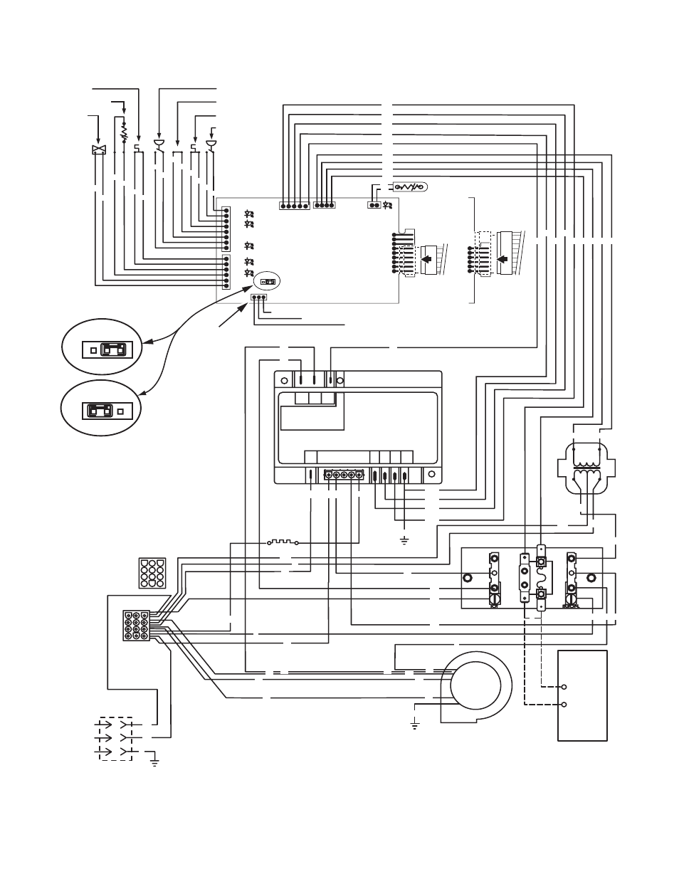
Pool Heater Wiring Connection Diagram
Plug –12 pin
120V – Black
240V – Red
JMP
9
1
J6
JMP
1
JMP
1
External Control Interface Circuit Disabled,
Heater Membrane Pad Enabled
External Control Interface Circuit
Enabled, "Pool On" and "Spa On"
Keys Disabled. "OFF" Key on
Membrane Pad Remains Functional.
CONNECTION DIAGRAM
AGS Switch
Stack Flue Sensor
Gas Valve
Air Flow Switch
Extra Switch 1
Hi-Limit Switch
Pressure Switch
VA
L
TH
IND
GND
24V
A
C
24V
A
C
FS
THERMIST
OR
OPERATING CONTROL
1
PS
HLS
ES1
AFS
AGS
SFS
GAS
MEMB RANE PAD
CONNECTIO N
Spa Line
Common Line
Pool Line
IGNITION CONT ROL
MODULE
DI AGNOSTIC INDI CATOR
F1
F2
24
VAC
S1
240
S1/
120
L1
L1
L2
BM
FL
F1
L2
S2
TH IND VAL GND
GND
GND
BLOWER
Line 2
120 VAC
IGNITER
TRAN S
Line 1
Ground
JUNCTION BOX
F
I
R
E
M
A
N
S
S
W
I
T
C
H
R
epla
ce
jum
p
er with
leads t
o
F
ir
e
man'
s
S
w
it
ch (field installed)
.
24 VAC
SEC
Y/W
Y/W
Y/R
Y/O
Y/BL
O
W
W
BK
BK
O
GY
GY
BK
BK
R
Y
BK
W
BL
Y
BK
W
BL
GY
GY
GY
GY
BK
BK
W
R
R
W
G
Y
R
R
Y
Y
Y
W
BK
Y/W
W
W
R
R
BL
BL
O
O
O
O
PR
PR
Y/R
Y/BL
Y/O
Y/W
Y
Y
Y
Y
Y
Y
Y
Y
Y
Y
BR
BR
3661 0200
External Control Interface
Y
NOTICE: Touching any 24VAC wire, including
the Fireman's Switch wire, to any 120/240V
terminal while the heater is connected to line
power will immediately destroy the control
board and void the warranty.
BK
R
GND
G
12 Position
Receptacle
1
NA/LP
Models Only
Y/R
Y/BL
Y/O
Y/W
NA/LP Models:
J6 incl. pins 1-6;
Connect 9-Wire
Cable as shown
6
1
J6