Adjusting 0 and 45 degree bevel positive stops – Porter-Cable 3802 User Manual
Page 13
13
13
ADJUSTING 0 AND 45 DEGREE BEVEL
POSITIVE STOPS
1.
DISCONNECT THE SAW FROM THE POWER
SOURCE.
2.
Adjust saw so that both bevel and miter pointers are
set at 0 degrees. Tighten bevel lock handle and lock
cuttinghead in down position.
3.
Place one end of a square (A) Fig. 27 on the table
and the other end against the blade. The blade should
be set at 90 degrees to the table.
4.
If an adjustment is necessary, loosen bevel lock
handle (H) Fig. 28. Loosen locknut (B) and turn adjusting
screw (C), with wrenches provided, until blade is 90
degrees to the table. Tighten locknut (B) and bevel lock
handle (H).
5.
When the blade is 90 degrees to the table, adjust
the pointer to line up with the 0 degree mark on the
bevel scale.
6.
Loosen bevel lock handle (H) Fig. 28, and move
cuttinghead all the way to the left bevel position and
tighten bevel lock handle.
7.
Use a square (A) Fig. 29, to see if the blade is at 45
degrees to the table.
8.
If an adjustment is necessary, loosen the bevel lock
handle. Loosen the locknut (E) Fig. 30, and turn the
adjusting screw (F), with wrenches provided, until the
blade is 45 degrees to the table. Tighten locknut (E) and
bevel lock handle.
9.
These positive stops enable you to rapidly position
the blade at the most common bevel angles to the table,
90 and 45 degrees.
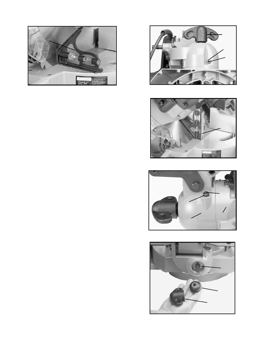
ADJUSTING SLIDING FIT BETWEEN
TRUNNION AND BEVEL BRACKET
After a long period of time, it may become necessary to
adjust the sliding fit between the trunnion (A) Fig. 30,
and the bevel bracket (B) by tightening adjusting nut (C),
Fig. 31, located underneath the bevel lock (A), Fig. 31,
and collar (B) Fig. 31.
Fig. 28
H
C
B
Fig. 29
A
Fig. 30
F
E
Fig. 31
C
A
B
A
B
Fig. 27
A