Location of controls – Panasonic VL-GC001A User Manual
Page 6
6
Introduction and Installation
Location of controls
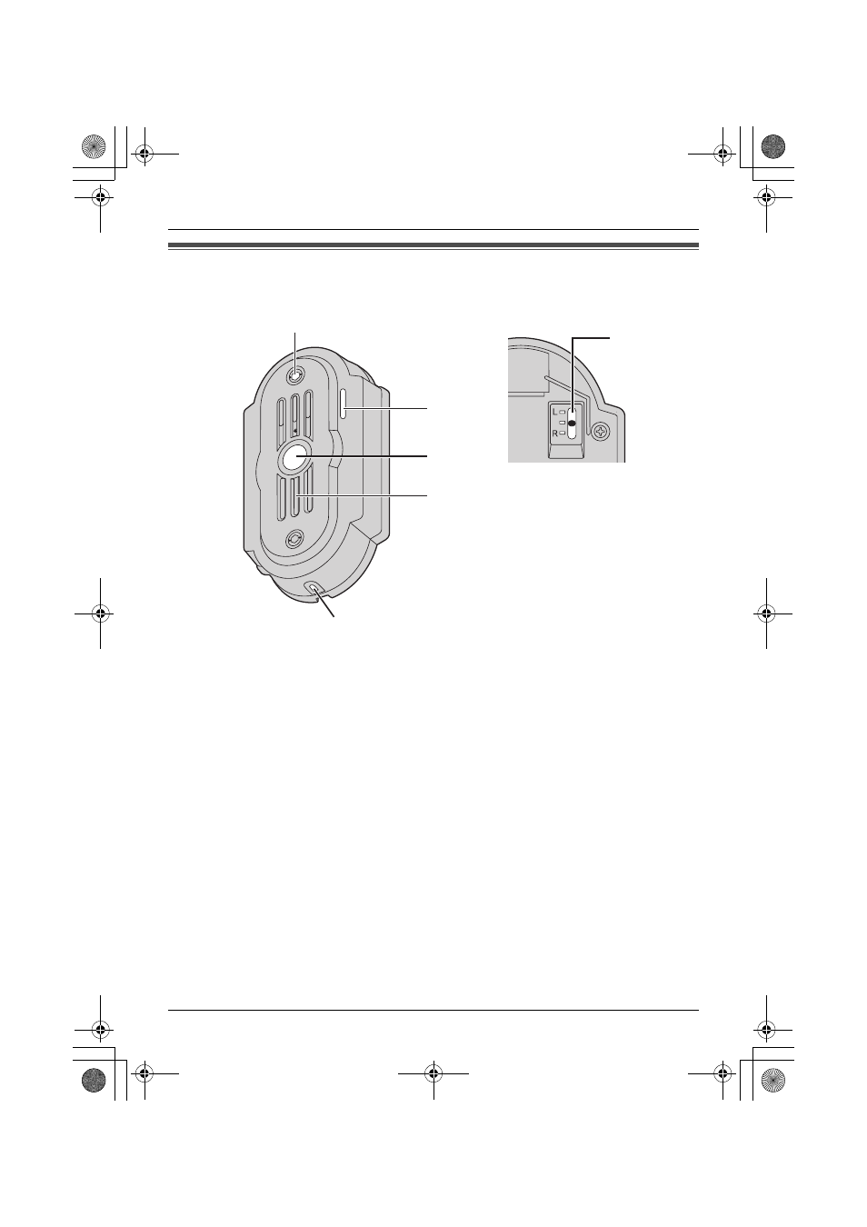
Front view
Rear view
A Camera
L
When a visitor presses the Call Button, the camera will turn on and an image of the
visitor will be shown on the display of the monitor station.
B Microphone
C Call Button
L
The Call Button is lit with a blue LED light while the power is on.
L
A visitor can press this button to call the monitor station.
D Speaker
E Water drain hole
L
This hole allows rain water to drain. Do not cover it.
F Camera angle control lever
L
The camera angle can be adjusted when installing the door station (page 7, 10).
A
B
E
F
C
D
VL-GC001A.book Page 6 Monday, February 28, 2005 12:08 PM
See also other documents in the category Panasonic Safety:
- 2318 (2 pages)
- BB-HCA10A (2 pages)
- Fire Alarm Systems Heat Detectors 6276 (2 pages)
- BB-HCM511A (2 pages)
- BL-WV10 (132 pages)
- 4375 (2 pages)
- 3377 (2 pages)
- 1828 (2 pages)
- 2217 (2 pages)
- Pod9cw (8 pages)
- 4301 (2 pages)
- 3378 (2 pages)
- 6362 (2 pages)
- EQ-500 Series (10 pages)
- 4300 (2 pages)
- 6295 (2 pages)
- 1550 (2 pages)
- 3333 (2 pages)
- BB-HCM580A (4 pages)
- WV-BP120 (22 pages)
- 1740 (2 pages)
- 6367 (2 pages)
- 3339 (2 pages)
- WV-BST504 (40 pages)
- 1826 (2 pages)
- 1728 (2 pages)
- 3312FL (2 pages)
- 1736 (2 pages)
- EY3796 (10 pages)
- EX-10 Series (13 pages)
- WJ-SQ508 (29 pages)
- 3309 (2 pages)
- MW-W20 (6 pages)
- EBL128 (2 pages)
- BB-HCM371 (2 pages)
- 4318 (2 pages)
- 4313 (2 pages)
- SUPER DYNAMIC III WV-NS202A (2 pages)
- Digital Fiber Sensor FX-301 (66 pages)
- 6363 (2 pages)
- MA Motion Sensor Series (11 pages)
- 1568 (2 pages)