Icolor accent powercore specifications, Installation steps for dmx control, Temperature monitoring – Philips iColor Accent Powercore User Manual
Page 2
5. Insert the terminator into the last fixture of each light series.
6. Repeat Steps 1 through 5 for each Data Enabler in the installation until
all lights are installed. (See Figure 3.)
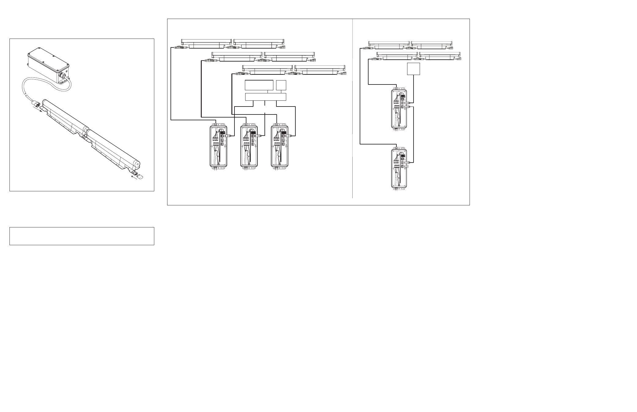
Connecting to lSM or VSM (for ethernet)
For Ethernet control, connect the iColor Accent Powercore fixtures and
the Data Enabler EO to the Light System Manager (LSM) or Video System
Manager (VSM) as described in the LSM or VSM User Guides.
Figure 4 shows the configuration.
installation Steps for dMX Control
1. Install the Data Enabler EO.
2. Install the fixtures.
3. Address the fixtures using QuickPlay Pro software.
4. Connect to a Philips Color Kinetics or third party DMX512 controller.
Each of these steps are described below.
installing the data enabler eO (for dMX)
See on page 1.
installing the Fixtures (for dMX)
See on page 1.
addressing the Fixtures (for dMX)
note
: Serial addressing gives you the option of post-installation addressing
multiple fixtures through a single Data Enabler or multiple Data Enablers
using the recorded serial numbers. Refer to the QuickPlay Pro Addressing
and Configuration Guide.
The iColor Accent Powercore fixtures are pre-addressed to light number
1 at the time of manufacture. Address each fixture with a new light number,
as needed, using QuickPlay Pro.
note
: During setup of a DMX installation, the QuickPlay Pro software
addresses the fixtures using an Ethernet connection between the PC and
the Data Enabler EO.
Download the QuickPlay Pro Addressing and Configuration Software and
instructions from www.colorkinetics.com/support/addressing.
1. With power disconnected, connect a single iColor Accent Powercore
fixture or a series of fixtures to a Data Enabler EO.
2. Connect the PC running QuickPlay Pro to the Ethernet Port on the
Data Enabler EO.
3. Connect power to the Data Enabler EO.
4. Use QuickPlay Pro to set the light address for each fixture.
Connecting to the dMX512 Controller
For DMX control, connect the iColor Accent Powercore fixtures and the
Data Enabler EO to the Color Kinetics or third party DMX512 controller
as described in the user documentation for the controller. (See Figure 4.)
iColor accent powercore Specifications
color
range
16.7 million additive RGB colors; continuously variable
intensity output range
output
50-100 lumens (estimated)
source
Chip-on-board RGB LEDs
visibility
range
250º x 180º
housing
Sealed plastic and extruded aluminum
weight
2-ft (0.61 m) - 4.5 lbs (2.0 kg)
4-ft (1.22 m) - 9.3 lbs (4.2 kg)
8-ft (2.44 m) - 18.0 lbs (8.2 kg)
connectors
Over-molded, integral male/female connectors
listings
UL / cUL, CE
COMMUniCatiOn SpeCiFiCatiOnS
data
interface
Philips Data Enabler EO (Item#106-000003-06)
control
Philips full line of controllers, including Video System
Manager, Light System Manager, and other DMX512 sources
eleCtriCal SpeCiFiCatiOnS
input
voltage
100 – 240 VAC 50 – 60 Hz
power
consumption
10 W per foot maximum
c
urrent
.1 A per foot maximum
enVirOnMental SpeCiFiCatiOnS
temperature
range
-4ºF to 122ºF ( -20ºC to 50ºC)
protection
rating
IP66
temperature Monitoring
For protection from extreme temperatures, the iColor Accent Powercore has been
designed with a temperature monitoring feature. If operating temperatures rise to
an unsafe level, a compensation circuit is triggered and the iColor Accent Powercore
operation is interrupted causing the lights to turn dull red.
To prevent additional power shut-downs, determine the cause of the overheating and
correct the problem. Power-cycle the system to return to full intensity.
50-foot (15.24 m)
leader cable
to first light in series
Data Enabler EO
Maximum Run length:
The lesser of 15 fixtures
or 100 feet (30.48 m)
Connectors are gender specific.
Ensure that all lights are installed
with connectors facing the same directions.
Female-to-Male
connection
Terminator
Always terminate last
light in series.
Figure 3
caution
: Ensure terminator is inserted into last fixture of each series.
Failure to do so may result in minor or moderate injury or property
damage and will void the warranty.
Figure 4
Ethernet
Switch
Ethernet IN
(CAT 5e / RJ45)
Light
System
Engine
PC*
Ethernet IN
(CAT 5e / RJ45)
Ethernet IN
(CAT 5e / RJ45)
ETHERNET DATA
Data Enabler EO
100 – 240 VAC
Data Enabler EO
100 – 240 VAC
Data Enabler EO
100 – 240 VAC
ETHERNET
DMX IN
DMX OU
T
ETHERNET
DMX IN
DMX OU
T
ETHERNET
DMX IN
DMX OU
T
BLUE
WH/BLU
E
OR
G
WH/ORG
BLUE
WH/BLU
E
OR
G
WH/ORG
BLUE
WH/BLU
E
OR
G
WH/ORG
* PC used for show
authoring and show control.
Maximum run length:
The lesser of 15 fixtures
or 100 feet
Video
System
Engine
- or -
ETHERNET
DMX IN
DMX OU
T
100 – 240 VAC
ETHERNET
DMX IN
DMX OU
T
BLUE
WH/BLU
E
OR
G
WH/ORG
DMX OUT
DMX IN
(CAT 5 / RJ45)
DMX IN
Terminator
(CAT 5 / RJ45)
DMX DATA
Data
Enabler
EO
100 – 240 VAC
DMX
Controller
BLUE
WH/BLU
E
OR
G
WH/OR
G
Maximum run length:
The lesser of 15 fixtures
or 100 feet
Data
Enabler
EO