Controls and settings – Phonic 17 User Manual
Page 7
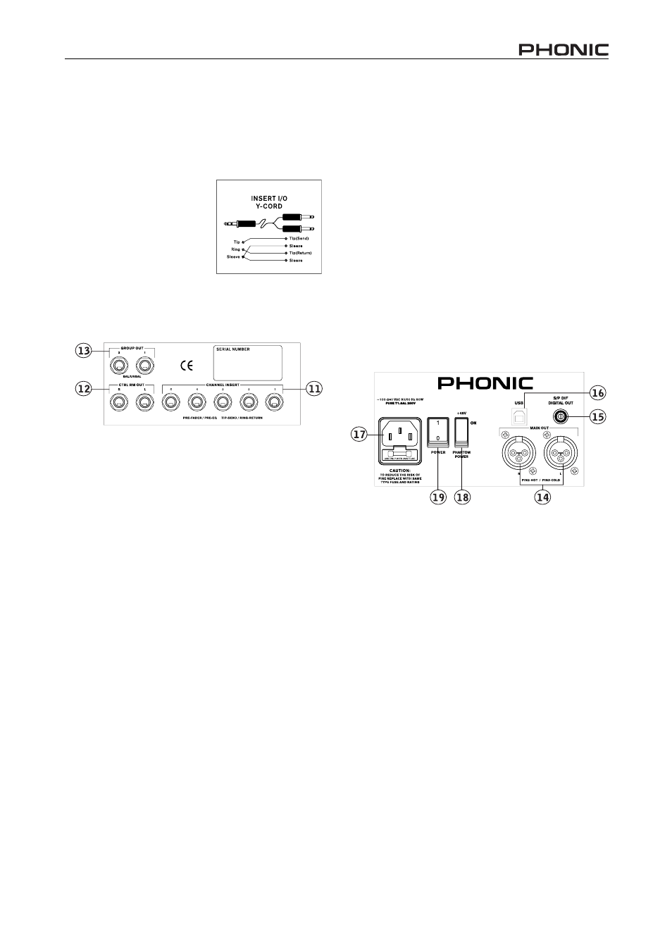
Rear Panel
11. Channel Inserts
Located on the rear of the Helix Board 17, the primary use
for these TRS phone jacks is for the addition of external
devices, such as dynamic processors or equalizers, to
mono input channels 1 through to 5. This will require a Y
cord that can send (pre-fader
and pre-EQ) and receive sig-
nals to and from an external
processor. The tip of the TRS
end of the Y cord is used to
send the signal to an external
device, whereas the ring is
used to return the signal back
to the Helix Board 17.
12. Control Room Outputs
These two balanced 1/4" TRS phone jack outputs feed the
signal altered by the Control Room / Phones level control
on the face of the mixer. This output has extensive use,
as it can be used to feed the signal from the mixer to an
active monitor, for the monitoring of the audio signal from
within a booth, or, alternatively, for the addition of external
signal processing devices or mixers, as well as acting as
a “side fi ll” output, supplying audio to indoor areas that the
main speakers do not reach.
13. Group Out
These balanced 1/4" TRS phone jacks output the fi nal feed
from the Group 1 and 2 Faders on the main mixer. These
outputs can be used to feed a wide range of devices,
such as mixers, signal processors, and even to connect
an amplifi er and speakers to be used along with the Main
Speakers, for a more rounded audio experience.
NB. When sending unbalanced signals from this output, a 1/4
"
TRS
stereo plugs must be used and have the ring-pin disconnected, as to
avoid damaging this mixer.
14. Main Output
These two XLR ports will output the fi nal stereo line level
signal sent from the main mixing bus. The primary purpose
of these jacks is to send the main output to external de-
vices, which may include power amplifi ers (and in-turn, a
pair of speakers), other mixers, as well as a wide range of
other possible signal processors (equalizers, crossovers,
etcetera).
15. S/PDIF Out
This RCA S/PDIF (Sony/Phillips Digital Interface - 16-bit,
with a 44.1 kHz sampling rate) output jack allows users
to connect their Helix Board 17 mixer to a multitude of
external digital audio equipment, most commonly DAT
recorders or digital processors. It allows the main signal
of your Helix Board 17 to be sent to other digital devices
without having to convert the signal from digital to analog,
and back again, effectively reducing the degredation of
the audio signal.
16. USB Port
This port allows users to use a USB cord to connect to
their Personal Computers or Laptops. This allows stereo,
2-way communication between your Helix Board 17 mixer
and your computer.
17. Power Connector
This port is for the addition of a power cable, allowing
power to be supplied to the mixer. Please use the power
cable that is included with this mixer only.
Controls and Settings
Rear Panel
18. Phantom Power Switch
When this switch is in the on position, it activates +48V of
phantom power for all microphone inputs, allowing con-
denser microphones (well, the ones that don’t use batteries)
to be used on these channels. Activating Phantom Power
will be accompanied by an illuminated LED above the left
channel Level Meter. Before turning Phantom Power on,
turn all level controls to a minimum to avoid the possibility
of a ghastly popping sound from the speakers.
NB. Phantom Power should be used in conjunction with balanced
microphones. When Phantom Power is engaged, single ended
(unbalanced) microphones and instruments should not be used on the
Mic inputs. Phantom Power will not cause damage to most dynamic
microphones, however if unsure, the microphone’s user manual should
be consulted.
19. Power Switch
This switch is used to turn the mixer on and off . Ensure
you turn all level controls down before activating.
7
HELIX BOARD 17