Warning, Aq q a – Peerless Industries A100IWBMOUNT User Manual
Page 5
ISSUED: 04-08-08 SHEET #: 055-9094-2 06-06-08
Visit the Peerless Web Site at www.peerlessmounts.com
For customer care call 1-800-865-2112 or 708-865-8870.
5 of 16
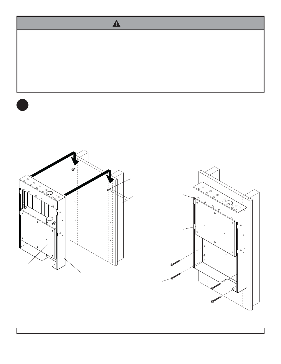
Make sure that the mounting holes are on the stud centerline. Drill six
5/32" (4 mm)
dia. holes 2-1/2" (65 mm) deep.
Fasten two #14 x 2.5" wood screws (Q) into top mounting holes leaving a .25" of exposed thread as shown. Hook
wall mount assembly (A) onto #14 x 2.5" wood screws (Q) as shown in fig. 2.1.
Fasten four #14 x 2.5" wood screws (Q) into wall mount assembly (A) as shown in fig. 2.2. Make sure that the wall
mount assembly (A) is level, tighten all six #14 x 2.5" wood screws (Q).
Skip to step 3.
Installation to Wood Stud Wall
• Installer must verify that the supporting surface will safely support the combined load of the equipment and all attached
hardware and components.
• Tighten wood screws so that wall plate is firmly attached, but do not overtighten. Overtightening can damage the
screws, greatly reducing their holding power.
• Never tighten in excess of 80 in. • lb (9 N.M.).
• Make sure that mounting screws are anchored into the center of the stud. The use of an "edge to edge" stud finder is
highly recommended.
• Hardware provided is for attachment of mount through standard thickness drywall or plaster into wood studs. Installers
are responsible to provide hardware for other types of mounting situations.
WARNING
2
fig. 2.1
fig. 2.2
CARRIAGE
CARRIAGE
.25"
A
Q
Q
A