Pin # label description – PowerDsine PD-6548 User Manual
Page 16
PD-6548
Power over Ethernet Solutions
16
Cat. No.: 06-6860-056
Table 2-6: Front Panel RJ45 Output Plug (per channel)
Pin #
Label
Description
1
P_RX+
Plus signal, Receive from DTE to PD
2
P_RX-
Minus signal, Receive from DTE to PD
3
P_TX+
Plus signal, Transmit from DTE to PD
4
Vdc (+)
Feeding power (+)
5
Vdc (+)
Feeding power (+)
6
P_TX-
Minus signal, Transmit from DTE to PD
7
Vdc (-)
Feeding power (-)
8
Vdc (-)
Feeding power (-)
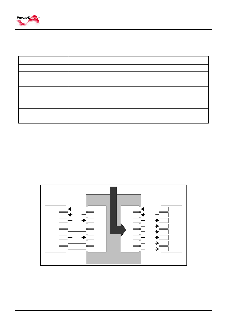
Each output port is configured as shown in Figure
2-3, as data pass-through
ports for all data pins (pins 1, 2, 3 and 6) and DC power addition on the spare
pins (pins 4, 5 , 7 and 8). Be certain to use Category 5 or higher cabling.
Figure
2-3 illustrates the Midspan functionality that adds DC power to the spare
pins.
DC -
1
2
3
4
5
6
7
8
1
2
3
4
5
6
7
8
1
2
3
4
5
6
7
8
1
2
3
4
5
6
7
8
RJ-IN
RJ-OUT
Ethernet
Switch
PD
RJ-45
RJ-45
Data
Data
Data
Data
Midspan Channel
Po
we
r B
u
s
Data
Data
Data
DC +
Data
DC -
DC +
Figure
2-3: Connecting to the Midspan