Side or bottom exhaust, Minimum clearances, Exhaust information (continued) – Panasonic VA-12020 User Manual
Page 4
• Detach and remove the desired knockout.
• Remove the screw inside the dryer exhaust duct end.
Keep the screw for step 5. Pull on the duct to remove it.
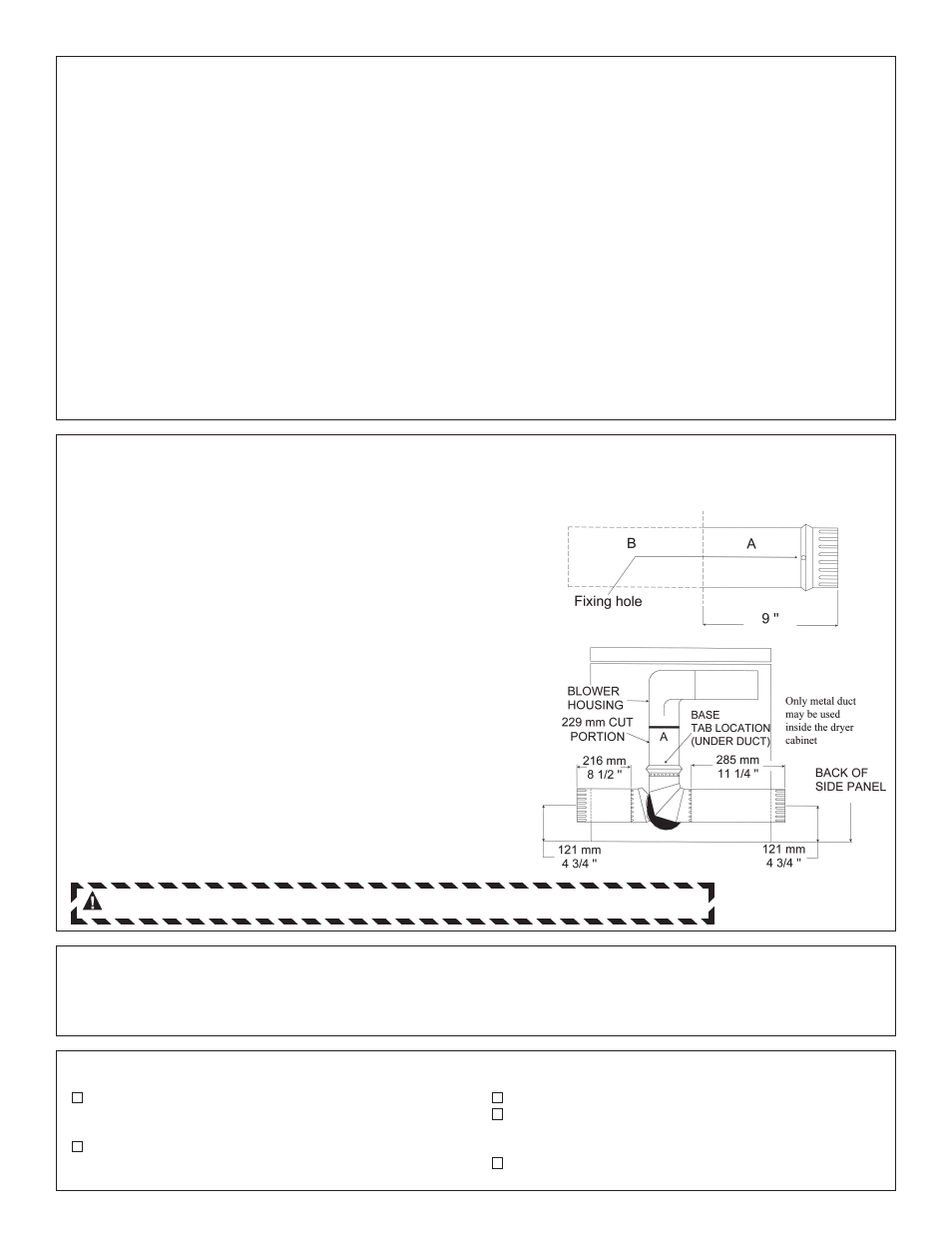
• Cut the duct as shown. Keep portion A.
• Through the rear opening, locate the tab in the middle of
the dryer base. Lift the tab to about 45˚ using a flat
screwdriver.
• Reconnect and secure the cut portion (A) of the duct to
the blower housing. Make sure that the fixing hole is
aligned with the tab in the base. Use the screw of item 2
to secure the duct in place through the tab on the dryer
base.
• Use standard metal elbows and duct to complete
exhaust system. Insert standard elbow and ducts
through rear and side or bottom openings.
• Cover the opening at the back with the plate (Kit
WE1M454) available from your Local Service Provider.
SIDE OR BOTTOM EXHAUST
STEPS TO CHANGE DRYER TO SIDE OR BOTTOM EXHAUST DIRECTLY ON CABINET
NOTE: Protect your hands and arms from sharp edges when working inside dryer cabinet.
Minimum clearances are – 0" both sides
– 1" at rear
– 88" vertical space from floor to ceiling
MINIMUM CLEARANCES
EXHAUST SYSTEM CHECK LIST
HOOD OR WALL CAP
• Terminate in a manner to prevent back drafts or
entry of birds or other wildlife.
• Termination should present minimal resistance to the
exhaust air flow and should require little or no
maintenance to prevent clogging.
• Wall caps must be installed at least 12" above
ground level or any other obstruction with the
opening pointed down.
SEPARATION OF TURNS
Separate all turns by at least 3 ft. of straight duct,
including distance between last turn and dampered
wall cap. If two turns must be closer than 3 ft., deduct
10 ft. from the maximum lengths shown in the table for
each occurrence.
TURNS OTHER THAN 90˚
• One turn of 45˚ or less may be ignored.
• Two 45˚ turns should be treated as one 90˚.
• Each turn over 45˚ should be treated as one 90˚.
SEALING OF JOINTS
• All joints should be tight to avoid leaks. The male
end of each section of duct must point away from
the dryer.
• Do not assemble the duct work with fasteners that
extend into the duct. They will serve as a collection
point for lint.
• Duct joints can be made air and moisture-tight by
wrapping the overlapped joints with duct tape.
INSULATION
Duct work which runs through an unheated area or is
near an air conditioning duct should be insulated to
reduce condensation and lint build up and be sloped
down toward outdoors.
NOTE: Never install screen inside exhaust duct.
EXHAUST INFORMATION (continued)
Note to Installer:
After Installation check the following:
Exhaust Duct - must meet specs as mentioned in
“Exhaust Information” section of this installation
instructions.
Grounding - Dryer must be properly grounded to
conform to local codes and ordinance
requirements.
Operation - Turn dryer ON and check for heat.
Hand Customer the Use and Care Book - Give
instructions on operating the dryer - answer any
questions.
Give these Installation Instructions to the customer.
WARNING: NEVER LEAVE THE BACK OPENING WITHOUT THE PLATE.