Pride Mobility Dynamic DX User Manual
Page 5
SCR
Basic Operation Manual
5
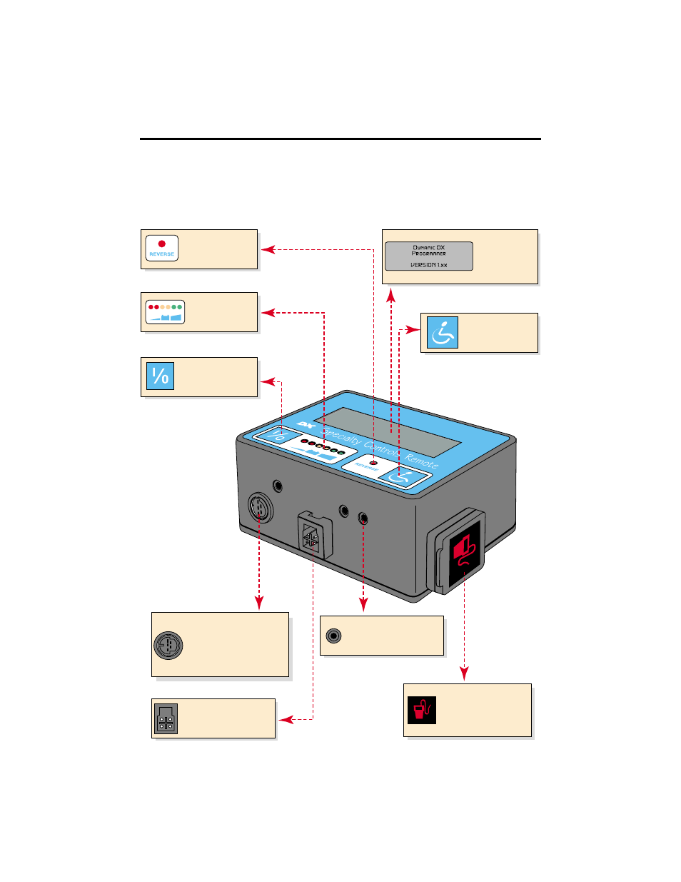
Figure 1. SCR Components and Connections
Mode Switch
Cycles through the
programmed modes.
LCD Display
4-line, 20 character
backlit LCD which
shows all functions
and instructions.
On/Off Switch
Toggles the entire DX
control system between
the On & Off modes.
Battery Meter
Battery charge level
is indicated by a
set of six LEDs.
Reverse Indicator
Disregard - this is a non-
functioning feature.
HHP/Wizard Port
Allows connection to an IBM
computer for custom
programming and where
standard drive programming
occurs with the HHP.
DXBUS Socket
For connecting the DX Remote
with a DXBUS cable to other
DX compatible modules
Battery Charger Port
Standard 3-pin XLR type
battery charger socket used
with off-board charging
systems.
External Switch Jacks
Three 3.5 mm (1/8") jack
sockets to allow connection of
external switches
Figure 1 provides information on the SCR components and connections.
Use this diagram to familiarize yourself with the function and location of
each component before using the SCR.