Danger – Partner Tech T330+ User Manual
Page 6
6
Locking/Release
Button in Primary Hole
Secondary Hole
For optional attachments, see the AS-
SEMBLY section of the applicable attach-
ment instruction manual.
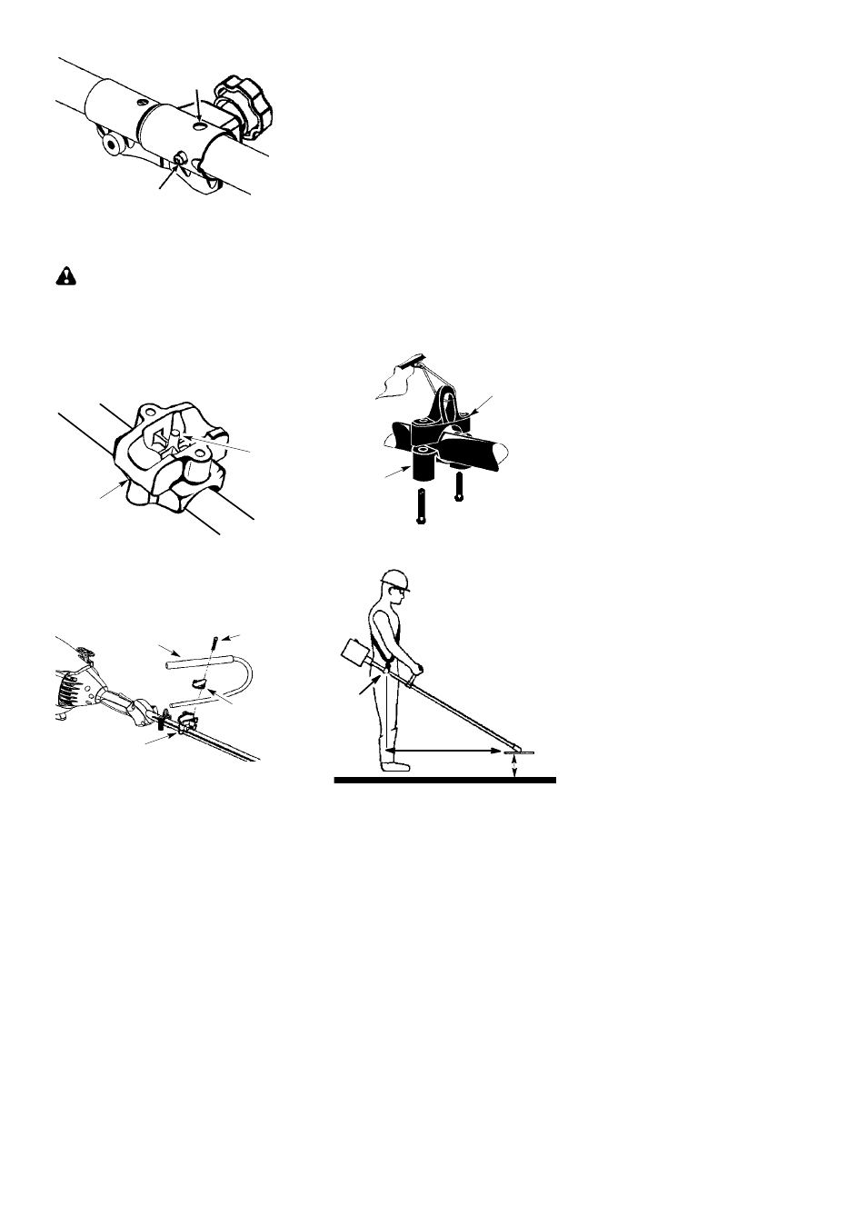
ATTACHING THE HANDLEBAR
DANGER:
To avoid serious injury, the
barrier portion of the handlebar must be installed
as shown to provide a barrier between operator
and the spinning blade.
1. Locate the decal on the handlebar. This
decal includes an arrow. Position the han-
dlebar with the mounting bracket at the
end of the arrow.
2. Align hole in handlebar with pin on mount-
ing bracket.
Pin
Mounting
Bracket
3. Position the bracket cover over the han-
dlebar. Again make sure the handlebar is
at the end of the arrow.
4. Insert screws and hand tighten only. Be
sure the handlebar is installed correctly;
then, tighten each screw securely with
the hex wrench.
Screw
Mounting
Bracket
Handlebar
Bracket Cover
ASSEMBLY OF SHOULDER STRAP
Proper shoulder strap and handlebar adjust-
ments must be made with the engine com-
pletely stopped before using unit.
1. Insert your right arm and head through the
shoulder strap and allow it to rest on your
left shoulder. Make sure the danger sign
is on your back and the hook is to the right
side of your waist.
NOTE:
A one-half twist is built in the shoul-
der strap to allow the strap to rest flat on the
shoulder.
2. Adjust the strap, allowing the hook to be
about 6 inches (15 cm) below the waist.
3. Fasten the strap hook to the clamp located
between the trigger handle and the handle-
bar clamp base and lift the tool to the operat-
ing position.
4. Try on shoulder strap and adjust for fit and
balance before starting the engine or be-
ginning a cutting operation.
NOTE:
It may be necessary to relocate the
shoulder strap clamp on the shaft for proper
balancing of unit.
TO RELOCATE SHOULDER STRAP
CLAMP:
1. Loosen and remove both clamp screws.
2. Place the upper shoulder strap clamp
over the shaft.
3. Position the lower shoulder strap clamp
under the shaft and align the upper and
lower clamp screw holes.
Upper Shoulder
Strap Clamp
Screws
Lower Shoulder
Strap Clamp
4. Insert two screws into the screw holes.
5. Secure shoulder strap clamp by tighten-
ing screws with a hex wrench.
76 cm
HARNESS
ADJUSTMENT
FOR BALANCE
10 -- 30 cm
above
ground
15 cm
below
waist