Signal ground lift jumper, Com out, Model cc-stl – Peavey CKS Series User Manual
Page 10: Network module installation diagram, Input module replacement diagram - nc-ipn
Page 8
Crest Audio CK Power Processing Amplifiers
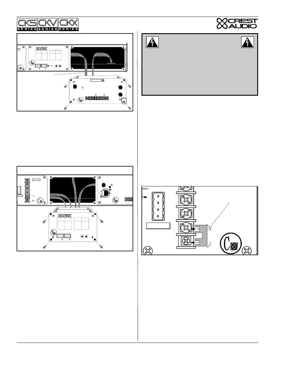
Replacing or Installing a Network Module.
The amplifier must be switched off and unplugged from the AC
mains supply before this operation is undertaken. Four Phillips head
screws secure the module to the chassis. The module is connected
electrically to the amplifier via multi-pin ribbon cables. Unplugging
the module from the ribbon cable connectors frees the module for
removal. To insert the same or another module, simply reverse this
procedure. Note: Standard CK Power Processing amplifiers come
with a blank panel installed in the Network bay. The amplifier must
not be operated without a Network module or blank panel in place.
Signal Ground Lift Jumper.
Whenever possible, the signal source equipment should share the
same AC ground as the amplifier(s). In some cases, however, partic-
ularly if an amplifier is being installed in an existing system, this
may result in a ground loop. If this happens, remove the factory-
installed ground lift jumper from the output barrier strip (located on
the Power/Output module), which electrically connects the signal
ground to the chassis/AC ground. If the jumper is removed, the sig-
nal ground is lifted and is clamped to ± 0.6V. Don’t remove the
jumper if the amplifier and the signal source equipment are not on
the same AC ground!
In a properly designed system (for safety and to minimize noise), the
amplifier should receive its ground from the AC line cord. The shield
on a balanced input line should be grounded at one end only (usually
the sending end), and it must never be relied on to supply AC ground
to the amplifier.
Com
Out
In
+8 to 18VDC
240 mA
Model
CC-STL
NEC
CLASS 2 ONLY
A
B
+
+
–
Signal
Ground
Lift
Jumper
Signal Ground
Lift Jumper
Model
NC-NXS
Hi
Data
Lo
Network
Address
0
8
1
9
2
A
3
B
4
C
5
D
6
E
7
F
0
8
1
9
2
A
3
B
4
C
5
D
6
E
7
F
Model
Name
CKS 100
CKS 200
CKS 400
CKS 800
CKS 800-2
CKS 1200-2
CKS 1600-2
Output Power
@8
Ω
/Ch.
50W
100W
200W
400W
400W
600W
800W
Crest Audio Inc.
100 Eisenhower Dr.
Paramus, New Jersey 07652 USA
Designed & manufactured in the USA by:
+
–
+
–
Model
Name
CKV 100
CKV 200
CKV 400
CKV 800
CKV 1600
CKV 2400
Output Power
@70.7V
50W
100W
200W
400W
800W
1200W
NEC
CLASS 2 ONLY
+8 to 18VDC
20 mA
Model
CC-STL
CLASS 2 WIRING
MAY BE USED
Output
A
B
+
+
–
–
Signal
Ground
Lift
Jumper
PUSH
Error
AES/EBU
In
SEE INSTRUCTION M
N-Coder
Data
Port
Inpu
+
–
Network Module Installation Diagram.
IMPORTANT:
THE POWER/OUTPUT
MODULE IS NOT REMOVABLE. DO NOT
ATTEMPT TO REPLACE OR REMOVE A
POWER/OUTPUT MODULE !
This module can only be serviced by a Crest Audio-certified
service technician. Please consult your dealer or Crest Audio
representative for assistance. User-inflicted damage to this
module will invalidate your warranty.
Ribbon Cable from
Network Module, if fitted
Model
NC-IPN
+
+
Input A
Input B
–
–
7
8
9
5
2
0
1
3
4
6
10
7
8
9
5
2
0
1
3
4
6
10
N-Coder
Data
Port
Level
B
Level
A
SEE INSTRUCTION MANUAL
0
8
1
9
2
A
3
B
4
C
5
D
6
E
7
F
0
8
1
9
2
A
3
B
4
C
5
D
6
E
7
F
Model
Name
CKS 100
CKS 200
CKS 400
CKS 800
CKS 800-2
CKS 1200-2
CKS 1600-2
Output Power
@8
Ω
/Ch.
50W
100W
200W
400W
400W
600W
800W
Model
NC-NXS
Hi
Data
Lo
Crest Audio Inc.
100 Eisenhower Dr.
Paramus, New Jersey 07652 USA
Designed & manufactured in the USA by:
Network
+
–
+
–
Address
Model
Name
CKV 100
CKV 200
CKV 400
CKV 800
CKV 1600
CKV 2400
Output Power
@70.7V
50W
100W
200W
400W
800W
1200W
WIRING
E USED
ut
Input Module Replacement Diagram - NC-IPN.