Play, Main unit, The unit’s display – Panasonic DMR-BW500 User Manual
Page 13
13
RQT9131
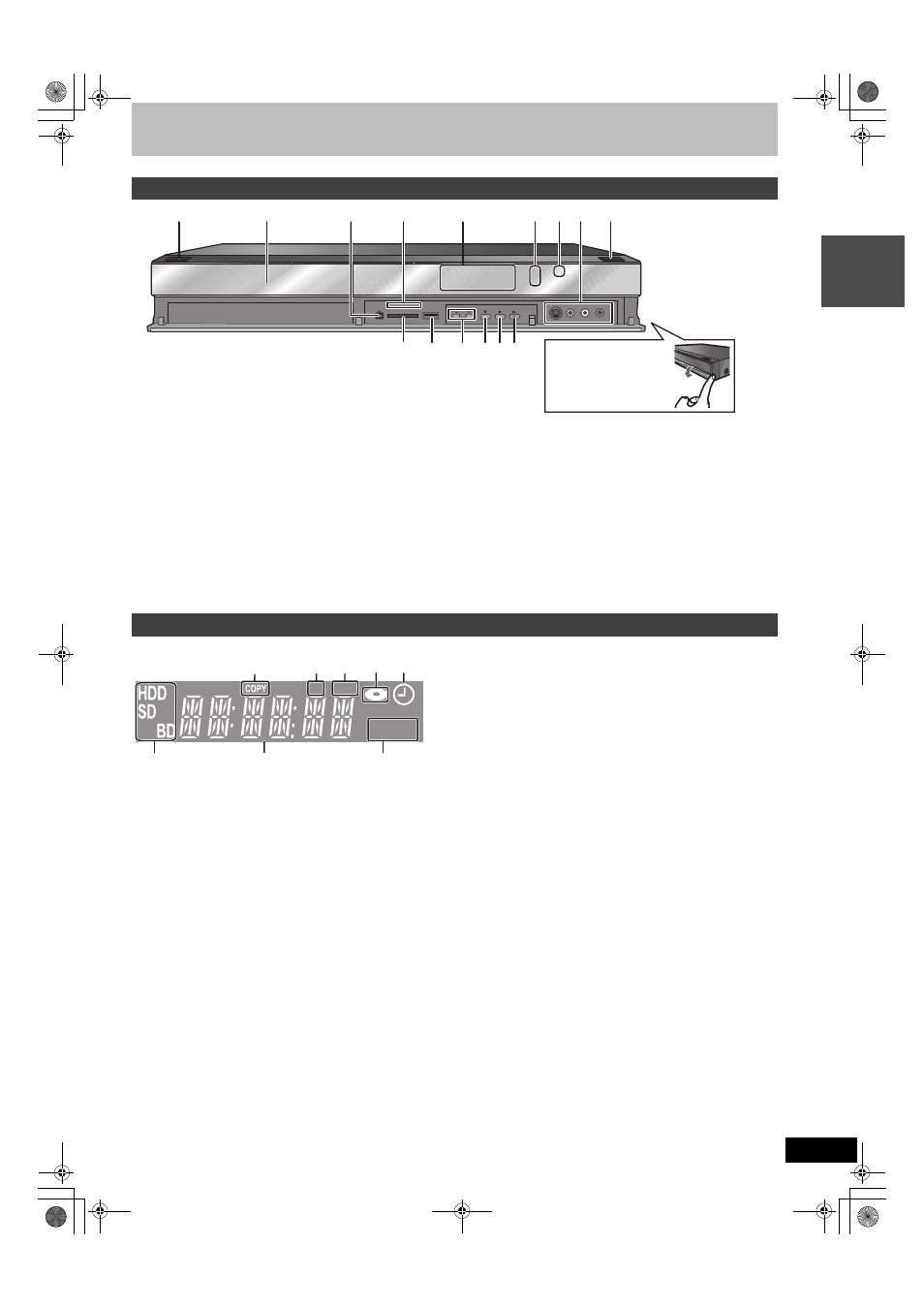
1Standby/on switch (
Í/I) (
➡ 18)
Press to switch the unit from on to standby mode or vice versa. In
standby mode, the unit is still consuming a small amount of power.
2Disc tray (
➡ 15)
3Connection for digital video (DV) camcorder (
➡ 56)
4SD Card LED
≥It is possible to set the LED to turn on/off. (
➡ 86, SD Card LED
Control)
5Display (
➡ below)
6Recording indicator
7Remote control signal sensor
8Connection for VCR, camcorder etc. (
➡ 55, 56)
9Open/close disc tray (
➡ 15)
:SD card slot (
➡ 15)
;USB port (
➡ 15)
➡ 23) =Start recording ( ➡ 23)/Specify a time to stop recording (➡ 23) >Stop ( ➡ 23, 38) ?Start play Rear panel terminals ( ➡ 16, 17, 94–98) 1Copying indicator ≥Indicators for functions that this unit does not support will not light. Main unit Pull to flip down the front The unit’s display PLAY SD USB Con tr o l r e fe re nc e guide DMRBW500GN-RQT9131-L_eng.book 13 ページ 2008年5月12日 月曜日 午前9時37分
2SD card slot indicator
3USB port indicator
4Disc indicator
5Timer recording indicator
6Drive (HDD, BD or SD) indicator
7Main display section indicator
8Playback indicator
panel.