M4 quick start guide, Caution, See chart below – Proficient Audio Systems M4 User Manual
Page 5: M4 specifications, Keypad hookup, Configure the keypad buttons, M4 fea tur es, General, Limited two-year warranty, M4 mul ti-z one aud io am plif ier /co ntr oller
16
15
14
M4 QUICK START GUIDE
M4 SpECIfICATIonS
For technical inquiries, please call 877.888.9004 or email us at
[email protected]. We are available to assist you every
weekday, except holidays, between the hours of 7:00 a.m. and 5:00 p.m. PST.
940 Columbia Avenue, Riverside, CA 92507
877.888.9004 • Fax 951.787.8747 • proficientaudio.com
Audio Sections
Rated Power/Channel
30 Watts, 20Hz - 20kHz
(RMS, 2 channels driven into 8 Ω)
THD (at rated power)
< 0.7%
Power/Channel
45 Watts @ 1kHz
(RMS, 2 channels driven into 4 Ω)
Input Sensitivity
300 mV
(For rated power @ max VC)
Input Impedance (source inputs)
> 22 kΩ
Input Overload (source inputs)
2.5 V
Output Voltage @ Pre-Outs
1.7 V, VC Setting, VC Max
(w/300 mV @ source inputs)
810 mV, NVC Setting
Output Impedance (pre-outs)
< 300 Ω
Frequency Response (@ 1 watt @ 8 Ω) 20Hz - 20kHz ± 1.5dB
Channel Separation
> 50dB @ 10kHz
Crosstalk Between Sources
> 65dB @ 10kHz
S/N Ratio (re: rated output,
> 95dB (VC 20dB IEC A,
source inputs shorted)
below FCW)
Bass Control Range
±10dB @ 100Hz
Treble Control Range
±10dB @ 10kHz
Control Sections
Contact Closures (dry)
2A, 30V AC/DC Max
Phone Page In
Audio Line Level, > 22 kΩ
– Voltage/Impedance
Doorbell/Status In 1 & 2, 10 mA @ 12V AC/DC
3V - 30V AC or DC
Common IR Out
– HI (high power)
9 V Active High, 82 Ω (110 mA Peak)
– LO (emitter power)
9 V Active High, 670 Ω (13 mA Peak)
Zone IR Outs
9.2 V Active High, 620 Ω (13 mA Peak)
– Voltage/Impedance
Source IR Outs (and loop) 11.5 V Active High, 390 Ω (29 mA Peak)
– Voltage/Impedance
Common Status Out
9.5 V @ 100 mA
(0-12V DC)
General
power Consumption
No Signal (idle)
50 Watts
At 1/8 Rated Power
110 Watts
(3.75 watts/channel)
Line Ratings (120V AC version)
120V AC, 1.8A
Rear Panel Fuse (120V AC version) T5AL 250V
Line Ratings (230V AC versions)
230V AC, 0.9A
Rear Panel Fuse (230V AC versions) T2.5AL 250V
Dimensions (H x W x D)
5
13
⁄
16
" x 171⁄8" x 15
1
⁄
2
"
148mm x 435mm x 394mm
Weight
20 lbs (9.1 kg)
Limited Two-Year Warranty
Proficient Audio Systems warrants to the original retail purchaser only that this product will
be free from defects in materials and workmanship for a period of two years, provided the
speaker was purchased from a Proficient Audio Systems Authorized Dealer.
Defective products must be shipped, prepaid and insured, together with proof of purchase,
to the Proficient Audio Systems Authorized Dealer from whom they were purchased, or to
Proficient Audio Systems at the address listed on this installation instruction manual. Freight
collect shipments will be refused. It is preferable to ship this product in the original shipping
container to lessen the chance of transit damage. In any case, the risk of loss or damage in transit
is to be borne by the purchaser.
If, upon examination at the Factory or Proficient Audio Systems Authorized Dealer, it is
determined that the unit was defective in materials or workmanship at any time during this
warranty period, Proficient Audio Systems or the Proficient Audio Systems Authorized Dealer
will, at its option, repair or replace this product at no additional charge, except as set forth
below. If this model is no longer available and can not be repaired effectively, Proficient Audio
Systems, at its sole option, may replace the unit with a current model of equal or greater value.
In some cases where a new model is substituted, a modification to the mounting surface may
be required. If mounting surface modification is required, Proficient Audio Systems assumes
no responsibility or liability for such modification. All replaced parts and product become the
property of Proficient Audio Systems. Products replaced or repaired under this Warranty will
be returned to the original retail purchaser, within a reasonable time, freight prepaid.
This Warranty does not include service or parts to repair damage caused by accident, disaster,
misuse, abuse, negligence, inadequate packing or shipping procedures, commercial use, volt-
age inputs in excess of the rated maximum of the unit, or service, repair or modification of the
product which has not been authorized or approved by Proficient Audio Systems. This Warranty
also excludes normal cosmetic deterioration caused by environmental conditions. This warranty
will be void if the Serial Number on the product has been removed, tampered with or defaced.
This Warranty is in lieu of all other expressed warranties. If the product is defective in materials
or workmanship as warranted above, the purchaser’s sole remedy shall be repair or replacement
as provided above. In no event will Proficient Audio Systems be liable for any incidental or con-
sequential damages arising out of the use or inability to use the product, even if Proficient Audio
Systems, or a Proficient Audio Systems Authorized Dealer has been advised of the possibility of
such damages, or for any claim by any other party. Some states do not allow the exclusion or
limitation of consequential damages, so the above limitation and exclusion may not apply.
All implied warranties on the product are limited to the duration of this expressed Warranty.
Some states do not allow limitation on the length of an implied warranty. If the original retail
purchaser resides in such a state, this limitation does not apply.
ZonE STATUS LEDS
LED indicators and labels:
Four blue LEDs indicate
that one or more zones
are currently active.
MASTER poWER SWITCh
When pressed in, the M4
permits zones to be turned
ON and OFF by keypad or
touch panel commands.
BLUE InDICAToR LIGhT
Blue indicates the master
power switch is ON and one
or more zones are active.
Red is OFF.
Keypad RJ45
T568B Standard
T568A Standard
12V
Pin 2, 7 Orange, White/Brown Green, White/Brown
DATA/IR Pin 4, 5 Blue, White/Blue Blue, White/Blue
GND
Pin 1, 8 White/Orange, Brown White/Green, Brown
485A
Pin 3
White/Green
White/Orange
485B
Pin 6
Green
Orange
1 2 3 4 5 6 7 8
T568A Standard
1 2 3 4 5 6 7 8
T568B Standard
SPKRS
L
R +
+ – –
ZONE 4
L
R
PRE-OUT
VC
NVC
KEYPAD
IR OUT
PMKIR
Master Keypad
with IR Receiver
A
D
D
R
ES
S
KEYPAD EXPANSIO
N
Riverside, CA. USA • Made in China
proficientaudio.com
+ RELA
Y
–
RELAY
+12V
DATA
GND
485
A
485
B
M4
Keypad
Connector
Rear View
CAUTION:
Colors shown are based on
T568B RJ45 termination.
SEE CHART BELOW
for T568A and T568B
wiring termination.
Inter-Room
Twisted Pair
CAT5 Cable
1,000' (305m) Max.
Orange
White/Brown
Blue
White/Blue
Brown
White/Orange
White/Green
Use Twisted Pair
for 485A & 485B
Green
figure 11 Ribbon Cable – PMKIR Right
figure 12 Ribbon Cable – PMKIR Left
KEYpAD hooKUp
noTE: The numeric and function keypads will not
work on their own. They must be connected to a
master keypad using the 3-connector ribbon cable
supplied (included with each model). The cable is
symmetrical so it can be connected with the red
striped side up or down, to best fit the configuration.
figure 11 shows it connected so that the PMKIR
master keypad will be to the right of the PNK numeric
and PFK function keypads when mounted, whereas
figure 12 places the PMKIR to the left.
figure 13 RJA-1.1 Adapter
figure 14 RJA-1.1 Attached to Keypad and CAT5
figure 15
Using CAT5 Cable to Connect PMKIR Keypads to M4
figure 10 Moving and Placing Buttons
figure 9 Remove Decorator Insert Panel
1. The keypads have a pre-installed set of buttons in
place. These may not match the source and function
arrangements you need or desire. To change them,
release the tabs on each end of the keypad, figure 8,
and remove the decorator insert panel, exposing the
key buttons, figure 9.
2. Starting with the Zone 1 PMKIR (master keypad),
and using the extra buttons supplied, if needed,
move and place the source and function buttons in
the arrangement you want. See figure 10. When you
finish the arrangement, replace the decorator insert
panel over the buttons, being careful to see that the
buttons align correctly with the panel openings.
Press the panel down until the tabs “snap” into place.
3. Repeat these steps for each of the other zone
master keypads. Each zone can have its own unique
configuration… but, it is best to keep them as similar
as possible to simplify programming and operation.
4. In the same way, configure the buttons on the
numeric and function keypads (not included) that
you may chose to use in some zones.
5. Connect all keypads to their assigned zones on
the M4 as shown in figure 7. Be sure to strip then
connect the various colored CAT5 leads to the correct
terminals on each keypad end. Refer to figure 15.
ConfIGURE ThE KEYpAD BUTTonS
noTE 1: If you want to use RJ45 connectors for
connecting the CAT5 cable to the keypads, you can do
so by using the Proficient model RJA-1.1 RJ45-to-Wire Pin
Adapters. See figure 13 and figure 14. Simply insert the
RJA-1.1 pins into the keypad’s connection terminals and
snap the levers in place. Be sure to orient them correctly
as shown.
figure 8 Release Tab
1301-72400 (rev1)
figure 1
M4 Front Panel Features
RS232
PHONE (PAGE IN)
DOORBELL / STATUS IN
1
2
CONTROL
PORT
FIRMWARE
UPGRADE
OFF ON
COMMON
IR OUT
LO
HI
STATUS OUT: 0 to +12V
120V 60Hz 1.
8A ~
FUSE: T5AL 250V
DATA I/O
CONTACT CLOSURE
EXPANSION PORTS
COMMON
M4
SOURCE 1
LOOP
OUT
IR
LOOP
L
R
INPUTS
SOURCE 2
LOOP
OUT
IR
LOOP
L
R
INPUTS
SOURCE 3
LOOP
OUT
IR
LOOP
L
R
INPUTS
SOURCE 4
LOOP
OUT
IR
LOOP
L
R
INPUTS
SOURCE 5
LOOP
OUT
IR
LOOP
L
R
INPUTS
SOURCE 6
LOOP
OUT
IR
LOOP
L
R
INPUTS
SPKRS
L
R+
+
–
–
ZONE 4
L
R
PRE-OUT
VC
NVC
KEYPAD
IR OUT
Riv
ers
ide
, C
A. U
SA
Made in Ta
iwan
SPKRS
L
R+
+
–
–
ZONE 3
L
R
PRE-OUT
VC
NVC
KEYPAD
IR OUT
SPKRS
L
R+
+
–
–
ZONE 2
L
R
PRE-OUT
VC
NVC
KEYPAD
IR OUT
SPKRS
L
R+
+
–
–
ZONE 1
L
R
PRE-OUT
VC
NVC
KEYPAD
IR OUT
5
4
3
2
M4
fEA
TUR
ES
M4
Mul
ti-Z
one
Aud
io
Am
plif
ier
/Co
ntr
oller
The
M4
is
a fo
ur-z
one
, si
x-s
our
ce
Aud
io
Am
plif
ier
/Co
ntr
olle
r. I
t se
rve
s as
the
“br
ain
s” o
f th
e en
tire
key
pad
syst
em
. Th
e M
4 pr
ovi
des
aud
io
sw
itc
hin
g fo
r
six
sou
rce
s an
d 30
W/c
han
nel
aud
io
pow
er a
mpl
ifie
rs
for
fou
r zo
nes
. It
als
o
has
con
nec
tio
n te
rm
ina
tio
n fa
cili
tie
s fo
r th
e co
ntr
olle
d w
hol
e ho
use
syst
em
.
Doo
RBE
LL/
STA
TU
S In
1
& 2
JAC
KS
The
se
3.5
mm
min
i ph
one
trig
ger
inp
uts
wor
k in
con
jun
ctio
n w
ith
the
PH
ON
E PA
GE
IN
jac
k.
Whe
n
trig
ger
ed,
the
pho
ne
inp
uts
can
be
tur
ned
on
as
prog
ram
med
by
pro
fic
ien
t Ed
ito
r. I
f au
dio
pag
ing
is
not
req
uire
d, t
hes
e 1
& 2
jac
ks
may
als
o be
pog
ram
med
as
STA
TU
S in
put
s fo
r po
wer
man
age
men
t of
sou
rce
or
zon
e co
mpo
nen
ts.
The
y ac
cep
t in
put
lev
els
of 3
V to
30V
AC
or DC
for
the
trig
ger
ON
con
diti
on.
The
vol
tag
e le
vel
must
dro
p be
low
1V
AC
or DC
for
the
OFF
con
diti
on.
IR
oU
T
Thi
s 3.
5m
m m
ini
jac
k, o
ne
for
eac
h zo
ne,
pro
vid
es
ded
ica
ted
Zon
e IR
out
put
ini
tia
ted
from
the
res
pec
tiv
e zo
ne
inp
uts
. Th
ey
may
con
tro
l
spe
cifi
c zo
ne
com
pon
ent
s w
hen
you
wan
t to
pre
ven
t th
e co
ntr
ol o
f it
from
the
oth
er z
one
s.
EXp
An
SIo
n p
oRT
S
RJ4
5 ja
cks
pro
vid
e fo
r co
nne
ctio
n
of s
pec
ial
ize
d RS
485
con
tro
lle
d
prod
uct
s an
d fo
r loo
pin
g to
add
itio
nal
M4
con
tro
lle
rs
for
zon
e
exp
ans
ion
cap
abi
lity
.
RS-
232
DAT
A I/
o
Com
mun
ica
tio
n po
rt.
ph
on
E p
AGE
In
JA
CK
Thi
s ja
ck
pro
vid
es i
npu
t p
orti
ng
for
au
dio
fe
eds
fro
m
doo
r m
ike
s o
r o
the
r fo
rm
s o
f p
hon
e o
r d
oor
bel
l
pag
ing
. T
he
jac
k is
pr
ogr
am
mab
le
by
pro
fic
ien
t
Edi
tor
, to
tu
rn
on
as e
ven
ts,
whe
n tr
igg
ere
d b
y th
e
DO
ORB
ELL
/ST
ATU
S IN
Ja
ck.
Co
nTA
CT
CLo
SU
RE
Pro
vid
es
a si
ngl
e po
le
dry
rel
ay
con
tac
t to
act
iva
te
any
dev
ice
tha
t
can
be
con
tro
lle
d or
trig
ger
ed
by
a
sw
itc
h cl
osu
re.
The
clo
sur
e ca
n be
prog
ram
med
with
in
pro
fic
ien
t Ed
ito
r
to
be
act
iva
ted
by
key
pad
pre
sse
s,
Com
man
d L
ibr
ary
IR
, o
r w
ith
in
mac
ros
for
M
om
ent
ary
, To
ggl
e a
nd
Ope
n/
Clo
se
Pai
red
op
era
tio
ns.
Spr
ing
-lo
ade
d
ter
min
als
acc
ept
w
ire
siz
es f
rom
28
to
14
AW
G. In
ter
nal
re
lay
co
nta
cts
ar
e ra
ted
at
2A/
30V
AC
or
D
C.
Co
nTR
oL
po
RT
& fI
RM
WAR
E U
pG
RA
DE
SW
ITC
h
3.5
mm
4-c
irc
uit
min
i ph
one
jac
k al
low
s se
ver
al c
ont
rol
func
tio
ns.
All
key
pad
prog
ram
min
g is
acc
om
plis
hed
via
thi
s po
rt u
sin
g pr
ofi
cie
nt E
dit
or i
n co
nju
nct
ion
with
the
mat
ing
Tra
nsf
er C
abl
e. I
t al
so
acc
om
mod
ate
s fa
cto
ry
firm
war
e up
dat
es
in
con
jun
ctio
n w
ith
the
fIR
MW
ARE
UpG
RA
DE
off
/o
n S
wit
ch.
Be
sur
e to
lea
ve
thi
s sw
itc
h in
the
off
po
siti
on
at a
ll t
im
es,
exc
ept
, as
inst
ruc
ted
with
in
pro
fic
ien
t
Edi
tor
, w
hen
you
are
doi
ng
a fir
mw
are
upd
ate
. Su
ch
upd
ate
s en
sur
e th
at y
ou
can
alw
ays
hav
e th
e la
test
func
tio
nal
ity
im
pro
vem
ent
s in
the
fie
ld.
Ano
the
r fu
nct
ion
of
thi
s po
rt i
s th
at y
ou
can
con
tro
l in
stal
led
syst
em
com
pon
ent
s w
ith
bi-d
ire
ctio
nal
dat
a vi
a to
uch
pan
els
or c
om
put
ers
usin
g RS
232
pro
toc
ol.
Co
MM
on
IR
oU
TpU
T &
hI/L
o S
WIT
Ch
3.5
mm
min
i ph
one
jac
k pr
ovi
des
a co
mm
on
IR
out
put
der
ive
d fr
om
all
of
the
zon
e IR
inp
uts
and
from
key
pad
ini
tia
ted
IR
com
man
ds
der
ive
d fr
om
the
int
ern
al I
R lib
rar
y. H
igh
or l
ow
IR
pow
er o
utp
ut i
s se
t by
mea
ns
of t
he
hI/L
o sw
itc
h. S
et i
t to
the
Lo
se
ttin
g w
hen
driv
ing
stan
dar
d lo
w po
wer
em
itt
ers
(i.e
, Pr
ofic
ien
t IR
sin
gle
fla
she
r).
Se
t it
to
the
hI p
osit
ion
whe
n
driv
ing
a hi
gh
pow
er e
mitt
er (
i.e
, a
bla
ster
) fo
r te
ach
ing
IR
com
man
ds
int
o
lea
rni
ng
rem
ote
s. C
aut
ion
: T
he
hI p
osit
ion
will
dam
age
or d
est
roy
low
pow
er e
mitt
ers
!
Co
MM
on
ST
ATU
S o
UT
po
RT
Thi
s 3.
5m
m m
ini
pho
ne
jac
k w
ill
go
hig
h (+
12V
DC)
whe
n an
y zo
ne
is
tur
ned
ON
and
will
go
LO
W (u
nde
r 1V
DC) w
hen
the
last
zon
e is
tur
ned
OFF
. T
he
max
. ou
tpu
t
of t
his
jac
k is
100
mA
at 9
.5V
DC.
IR
oU
T JA
CKS
The
se
3.5
mm
m
ini
ph
one
ja
cks
, o
ne
for
ea
ch
sou
rce
, p
rov
ide
ded
ica
ted
IR
ou
tpu
t to
sp
ecif
ic s
our
ce
com
pon
ent
s. W
hen
a
sou
rce
is
sel
ect
ed
on
a ke
ypa
d, I
R fu
nct
ion
com
man
ds
are
rou
ted
dire
ctly
to
tha
t so
urc
e. T
his
pre
ven
ts
cro
ss-
con
tro
l
int
erf
ere
nce
bet
wee
n tw
o or
mor
e so
urc
es
tha
t ha
ve
ide
ntic
al I
R co
mm
and
s.
IR
Lo
op
JAC
KS
The
se
six
3.
5m
m m
ini
ph
one
ja
cks
, o
ne
for
ea
ch
sou
rce
, a
re
pro
vid
ed
exc
lus
ive
ly
for
zo
ne
exp
ans
ion
ca
pab
ilit
y w
hen
usin
g tw
o or
mor
e M
4 co
ntr
olle
rs.
The
y pe
rm
it t
he
sou
rce
IR
sig
nal
s fr
om
the
add
ed
zon
es
to
be
car
rie
d to
the
sou
rce
com
pon
ent
em
itt
ers
.
L &
R A
UD
Io
In
&
Loo
p JA
CK
S
The
se
RCA
jac
ks
– fo
ur f
or e
ach
sou
rce
– pr
ovi
de
aud
io
sig
nal
inp
uts
and
buf
fer
ed
loo
p ou
tpu
ts,
for
eac
h
sou
rce
. Th
e bu
ffe
red
out
put
s ca
n be
use
d to
driv
e loc
al
com
pon
ent
s or
loo
p th
e si
gna
ls
to
the
add
itio
nal
zon
e
inp
uts
of o
the
r M
4 co
ntr
olle
rs
whe
n us
ing
the
m fo
r so
urc
e
exp
ans
ion
.
IEC
TY
pE
AC
Mai
ns
rec
ept
acl
e an
d fu
se
mat
es
with
inc
lud
ed
AC
pow
er c
ord
. A
lso
hou
ses
the
rea
r pa
nel
rep
lac
eab
le
AC
mai
ns
fuse
(T5
AL
250
V fo
r 12
0V,
and
T2.
5AL
250
V fo
r
230
V/2
40V
)
L &
R
pRE
-o
UT
JAC
KS
The
se
RCA
ja
cks
pr
ovi
de
lin
e le
vel
aud
io
out
put
s fo
r d
riv
ing
ex
ter
nal
pow
er a
mpl
ifie
rs
for
add
itio
nal
roo
ms
with
in
zon
es,
whe
re
nee
ded
.
VC-
nVC
SW
ITC
h
The
aud
io
out
put
from
the
PRE
-O
UT
jac
ks
can
eith
er b
e co
ntr
olle
d by
the
int
ern
al v
olu
me
con
tro
l of
the
M4
(V
C p
osit
ion
) or
be
a fix
ed
lin
e le
vel
out
put
in
the
no
vol
um
e co
ntr
ol
(n
VC
pos
itio
n).
In
eith
er c
ase
, th
e to
ne
con
tro
l
rem
ain
s av
aila
ble
for
roo
m “E
Q” s
ett
ing
s.
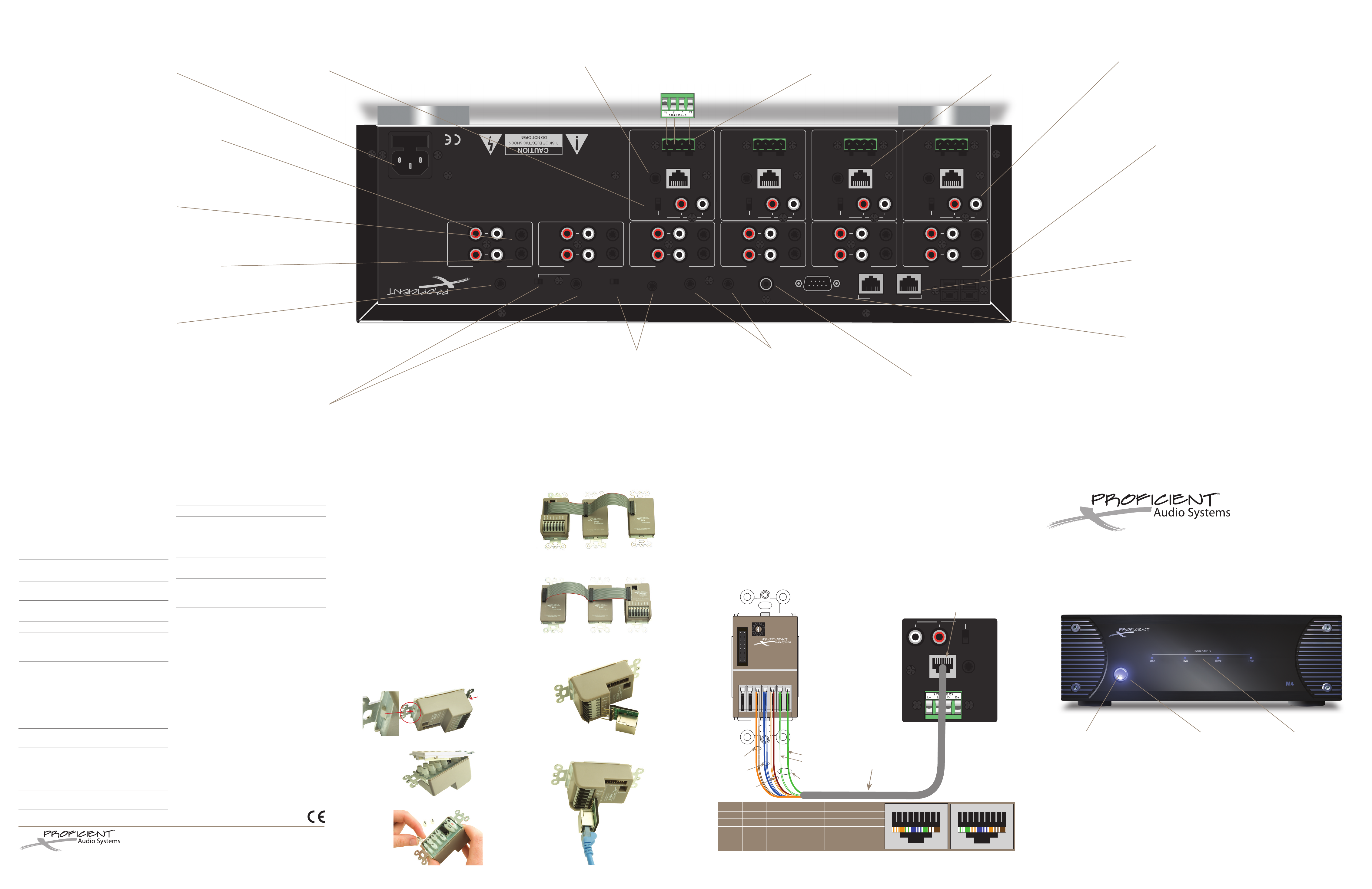
KEY
pAD
Zo
nE
In
pUT
S
The
se
RJ4
5 te
rm
ina
ls
allo
w fo
r e
asy
con
nec
tio
n o
f th
e in
ter
-ro
om
w
irin
g
fro
m k
eyp
ads
in
th
e v
ario
us r
oom
s.
Nor
mal
ly
thi
s is
ac
com
plis
hed
us
ing
CAT
5 c
abl
e w
ith
ho
me-
run
le
ngt
hs o
f
up
to
100
0'.
L &
R
SpE
AKE
RS
TER
MIn
ALS
The
se
4-c
irc
uit
plu
gab
le
scr
ew
-do
wn
ter
min
als
acc
ept
w
ire
si
zes
fro
m 1
4 to
28
AW
G. T
hey
al
low
qu
ick
co
nne
ctio
n o
f
the
in
ter
nal
am
plif
ier
s to
st
ere
o p
airs
of
spe
ake
rs i
n th
e v
ario
us z
one
ro
om
s.
fig
ure
2
M4
Rea
r Pa
nel
Fea
tur
es