Peavey 12/0280304941 User Manual
Page 7
7
A
AC
C P
Po
ow
we
err S
Sw
wiittcch
h/
/C
Ciirrccu
uiitt B
Brre
ea
ak
ke
err ((11))
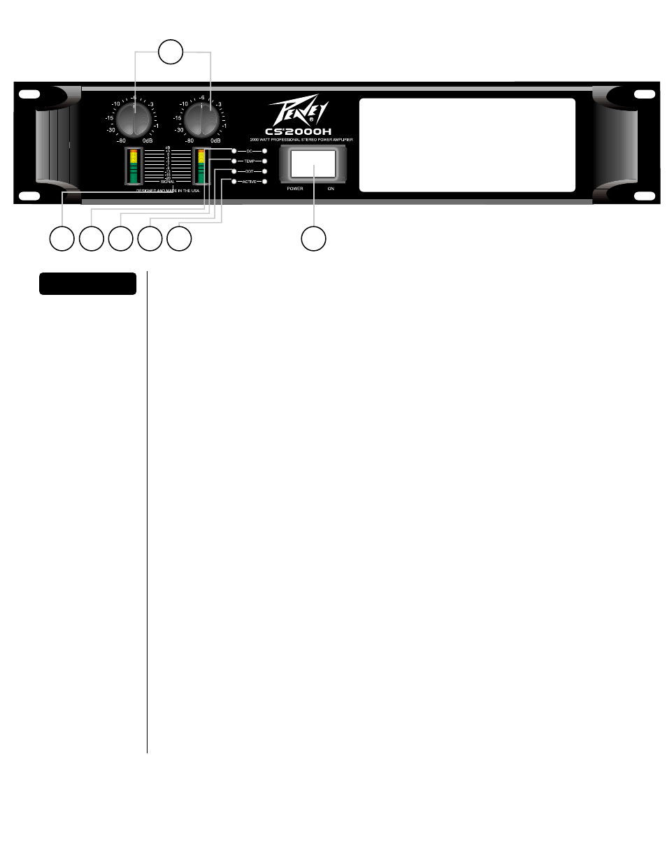
The CS 2000H amplifier has a combination AC switch/circuit breaker on the front panel. If the switch
shuts off during normal use, push it back to the ON position once. If it will not stay on, the amplifier
needs servicing.
IIn
np
pu
utt A
Atttte
en
nu
ua
atto
orrs
s ((2
2))
Whenever possible, set the attenuators fully clockwise to maintain optimum system headroom. The
input attenuator controls (one for channel A, one for channel B) located at the front panel adjust gain
for their respective amplifier channels in all modes. See the specifications at the end of this manual
for standard voltage gain and input sensitivity information.
When operating in the bridged mode, both attenuators must be in the same position so the speaker
load will be equally shared between the channels. See the section on B
Brriid
dg
ge
ed
d M
Mo
on
no
o Operation for
more information and precautions.
FFrro
on
ntt P
Pa
an
ne
ell IIn
nd
diicca
atto
orrss
The CS2000H features four front panel discreet LED indicators per channel: A
AC
CT
TIIV
VE
E, D
DD
DT
T, T
TE
EM
MP
P
and D
DC
C. These LED indicators inform the user of each channel’s operating status and warn of
possible abnormal conditions. This amplifier also features two 10-segment bar graph indicators
per channel: S
SIIG
GN
NA
ALL.
S
SIIG
GN
NA
AL
L L
LE
ED
D ((3
3))
This LED is at the bottom of the bar graph display and lights when its channel produces an output
signal of greater than 2 Volts RMS or 50 mV input with a 0 dB attenuation of the front panel knobs. It
is useful in determining whether a signal is reaching and being amplified by the amplifier. The 10-
segment graphs indicate the level of signal present.
D
DC
C L
LE
ED
D ((4
4))
The DC LED lights to indicate that the channel’s output relay is open, disconnecting the speaker(s)
when the amplifier senses a DC voltage or subsonic high level signal at its output.
T
TE
EM
MP
P L
LE
ED
D ((5
5))
The Temp LED lights to indicate that the channel’s output relay is open, disconnecting the speaker(s)
due to an overheating condition. Once the channel temperature has returned to safe operating
conditions the LED will turn off and the speaker(s) will be reconnected.
2
1
FFrro
on
ntt P
Pa
an
ne
ell
4
5
6
7
3