Assembly, Unpacking carton (see fig. 2), Install handle (see figs. 3, 4, and 5) – Poulan 403701 User Manual
Page 5
5
ASSEMBLY
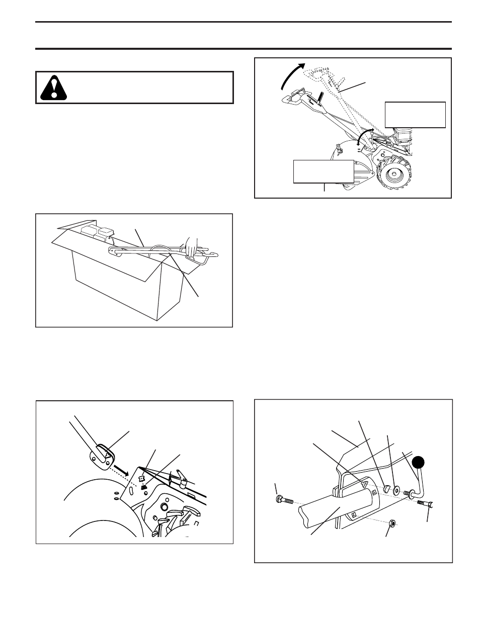
• Grasp handle assembly. Hold in “up” position. Be sure
handle lock remains in gearcase notch. Slide handle
assembly into position.
FIG. 4
UNPACKING CARTON (See Fig. 2)
CAUTION: Be careful of exposed
sta ples when handling or disposing
of cartoning material.
IMPORTANT: WHEN UN PACK ING AND AS SEM BLING TILLER,
BE CAREFUL NOT TO STRETCH OR KINK CABLES.
• While holding handle assembly, cut cable ties se cur ing
handle assembly to top frame and depth stake. Let
handle assembly rest on tiller.
• Remove top frame of carton.
• Slowly ease handle assembly up and place on top of
carton.
• Cut down right hand front and right hand rear cor ners
of carton, lay side carton wall down.
• Remove packing material from handle assembly.
FIG. 2
INSTALL HANDLE (See Figs. 3, 4, and 5)
• Insert one handle lock (with teeth facing outward) in
gearcase notch. (Apply grease on smooth side of
handle lock to aid in keeping lock in place until handle
assembly is lowered into position.)
FIG. 3
HANDLE ASSEMBLY
GEARCASE
NOTCH
HANDLE
LOCK
VIEWED FROM R.H. SIDE OF TILLER
handles_34
CARRIAGE
BOLT
SLOT
GEARCASE
HANDLE
LOCK
FLAT
WASHER
HANDLE LOCK
LEVER
PIVOT BOLT
LOCKNUT
HANDLE
BASE
FIG. 5
• Rotate handle assembly down. Insert rear carriage bolt
fi rst, with head of bolt on L.H. side of tiller and loosely
assemble locknut (See Fig. 5).
• Insert pivot bolt in front part of plate and tighten.
• Cut down remaining corners of carton and lay panels
fl at.
• Lower the handle assembly. Tighten nut on carriage
bolt so handle moves with some resistance. This will
allow for easier adjustment.
• Place fl at washer on threaded end of handle lock le-
ver.
• Insert handle lock lever through handle base and
gearcase. Screw in handle lock lever just enough to
hold lever in place.
• Insert second handle lock (with teeth inward) in the
slot of the handle base (just inside of washer).
• Raise handle assembly to highest position and se cure ly
tight en handle lock lever by rotating clockwise. Leav ing
han dle assembly in highest position will make it easier
to connect shift rod.
HANDLE ASSEMBLY
"UP" POSITION
car
ton
_1
SHIFT ROD
HANDLE
AS SEM BLY
TIGHTEN HANDLE
LOCK LEVER TO
HOLD
LOOSEN HANDLE
LOCK LEVER TO
MOVE