Pico Communications PICOPSU-90 User Manual
Page 3
Mini-Box.com
ATX DC-DC Converter Series
picoPSU-90 Quick Installation Guide
Page 3
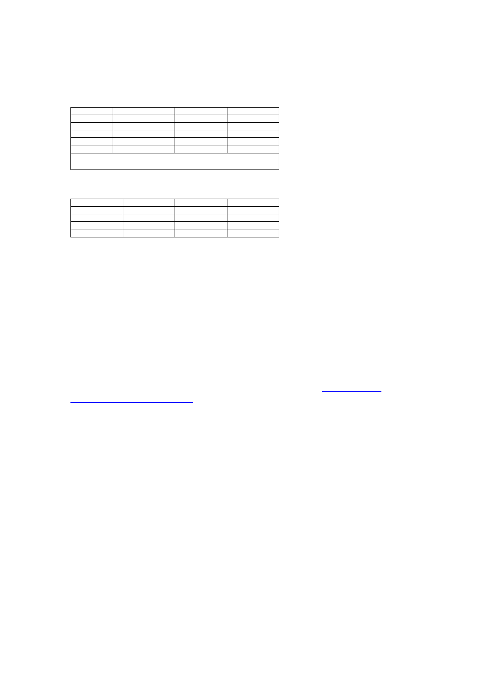
Specifications, picoPSU-90, 90Watts DC-DC ATX Power Supply
Power Ratings
Volts (V)
Max Load (A)
Peak Load (A)
Regulation %
5V
6A*
7A
+/- 1.5%
5VSB
1.5A
2A
+/- 1.5%
3.3V
5A*
7A
+/- 1.5%
-12V
0.05A
0.1A
+/- 5%
12V
5A
7A
Switched input
*At max load, forced air ventilation is required. For fanless or improper ventilation operation de-
rate the output of the 3.3 and 5V rails until PSU temperature falls below 65C. Peak load should
not exceed 60 seconds. Combined max power output should not exceed more than 90watts.
Efficiency Ratings, 3.3 and 5V rail
CH1=5V
Efficiency (%)
CH2=3.3V
Efficiency (%)
1A
86%
1A
85%
3A
95%
3A
94%
5A
93%
5A
92%
7A
85%
7A
85%
Input Requirements: 12V regulated, min=1A, max=10A (load dependent). Over-
voltage shutdown will occur at ~13-13.5V.
Size: 44.5mm(L) * 20mm(W) * 30mm (H) (1U compliant)
Weight: 45gramms, including cable harness, 20 grams without cable harness.
DC-Jack: Female, panel mount, 2.5*5.5*10 mm.
Connectors
Molex 39-01-2200 compatible, two 3.5” drive power connectors (PATA and
SATA) and one P4-12V 4 connector (mini-fit JR 4p). Header and mating
connector for the removable cable harness can be found at:
http://www.jst-
mfg.com/product/pdf/eEH.pdf
Overload protection
Over load protection will be effected when either of the loads (+5V & +3.3V)
exceeds > 150% Max Load.
Turn-on Delay
After turning on, at least 20 ms will be needed for the rise of +5VSB output
voltage (measured from 10% to 95%) to reach its peak.
Remote ON/OFF control (PS_ON)
Logic level is LOW - Output voltage is enabled (PS_ON pin)
Logic level is HIGH - Output voltage is disabled (PS_ON pin)
PWR_GD
Logic level is low: PWR_GD=OK
Logic level is high: PWR_GD=not OK (10.5V
conditions)