Speaker adjustments speaker installation, Painting the speakers – Proficient Audio Systems C790 User Manual
Page 2
The Ceiling Series speakers come from the factory with the
tweeter facing straight out from the baffle. This will result
in the overall smoothest response. However, depending on
your particular primary listening area, room acoustics, ceiling
height, or personal preference, you may find the sound more
pleasing by pointing the tweeters in a particular direction. If
additional treble is desired in the primary listening area, point
the tweeter towards that area; and if less treble is required,
point the tweeter away. Push gently at the edge of the tweeter
to point it in the desired direction. (See Diagram 2)
CAUTION: Avoid touching metal dome tweeters, as damage
may occur (C640, C645, C800, and C850).
Tweeter Adjustment (C640, C645, C800, & C850):
The switch labeled TREBLE allows for 3dB of treble adjustment.
Your speakers were shipped with the treble switch in the “–”
position, providing the most linear frequency response. If you
desire more treble, move the switch to the “+” position, and the
tweeter will play 3dB higher. To return to the neutral setting,
push the switch back to the “–” position. (See Diagram 3)
Woofer Adjustment (C640, C645, C800, & C850):
The switch labeled BASS allows for 3dB of bass adjustment.
Your speakers were shipped with the bass set to “–”. This set-
ting provides the flattest bass frequency response. If you desire
more bass, push the switch to the “+” position and the bass
will play 3dB higher. To return to the neutral setting, push the
switch back to the “–” position. (See Diagram 3)
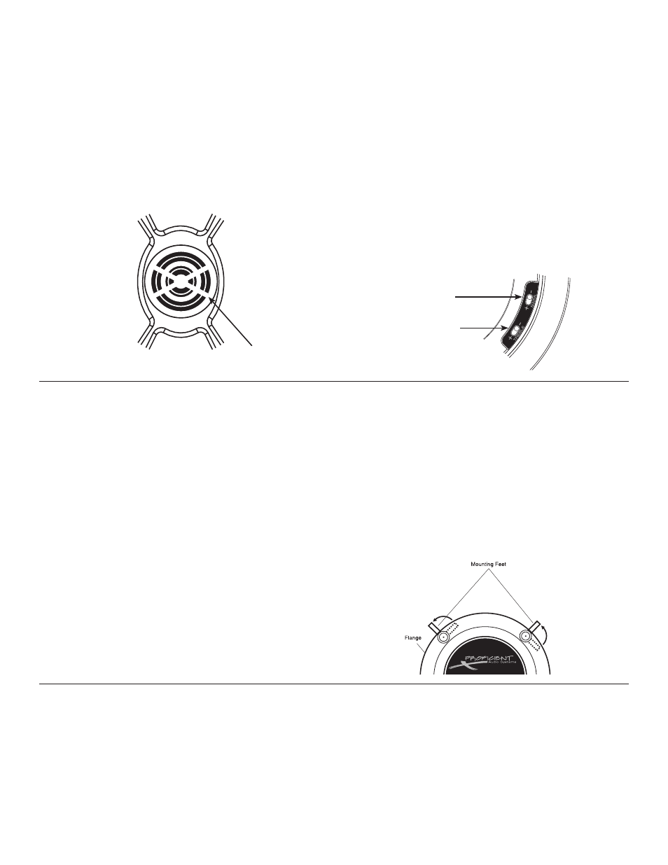
The unique integral four-foot mounting system incorporated
into each Ceiling Series speaker allows for a quick installation
by following these easy steps:
1. Remove the grille. It may be necessary to push one or two
of the mounting screws and its attached foot towards the
baffle and against the inside surface of the grille to force the
grille out of its retaining groove.
2. Attach the speaker cable (observing the proper polarity with
your amplifier, + to + and – to –). Make sure the left channel
of the amplifier is connected to the left speaker, and the right
channel is connected to the right speaker.
3. Make sure the mounting feet are turned inward to clear the
opening, and insert the speaker into the ceiling. Position the
speaker into the hole.
Note: The flange of the speaker is designed to flex and conform
to any small imperfections in the ceiling’s surface. Tighten the
four screws on the front of the baffle only enough to make the
flange become snug against the ceiling. As you tighten the
screws, the feet will automatically flip into an outward position
(See Diagram 4), thereby clamping the drywall between the feet
and the flange. CAUTION: Over-tightening may warp the
baffle, crack the ceiling, cause the flange to distort, and
make the grille difficult to install.
4. Push the grille firmly into the slot in the speaker baffle.
2
SPEAKER ADJUSTMENTS
SPEAKER INSTALLATION
Push Tweeter Here
Bass Adjustment Switch
Treble Adjustment Switch
If you plan to paint your speakers, we recommend that it be
done prior to installation. If you plan to paint your speakers
sometime in the future, it is best to remove them by simply
reversing the steps for “SPEAKER INSTALLATION” above.
If it is necessary to paint the speakers when they are in the
ceiling, the paint masks provided in the carton must be
installed between the grille and flange while they are being
painted with the ceiling.
Before painting your speakers, remove the white acoustic blan-
ket under the grilles. Once the speakers have been painted,
return the acoustic blanket back into place.
Great care should be taken not to clog the holes of the grille,
as this will reduce the sound quality of the speakers.
Proficient recommends only light spray painting using 5 parts
thinning agent to 1 part paint.
PAINTING THE SPEAKERS
Diagram 2:
Tweeter
Diagram 3:
Adjustment Switches
Diagram 4:
Mounting Feet