Porter-Cable PC1800AG User Manual
Page 14
14
Operation
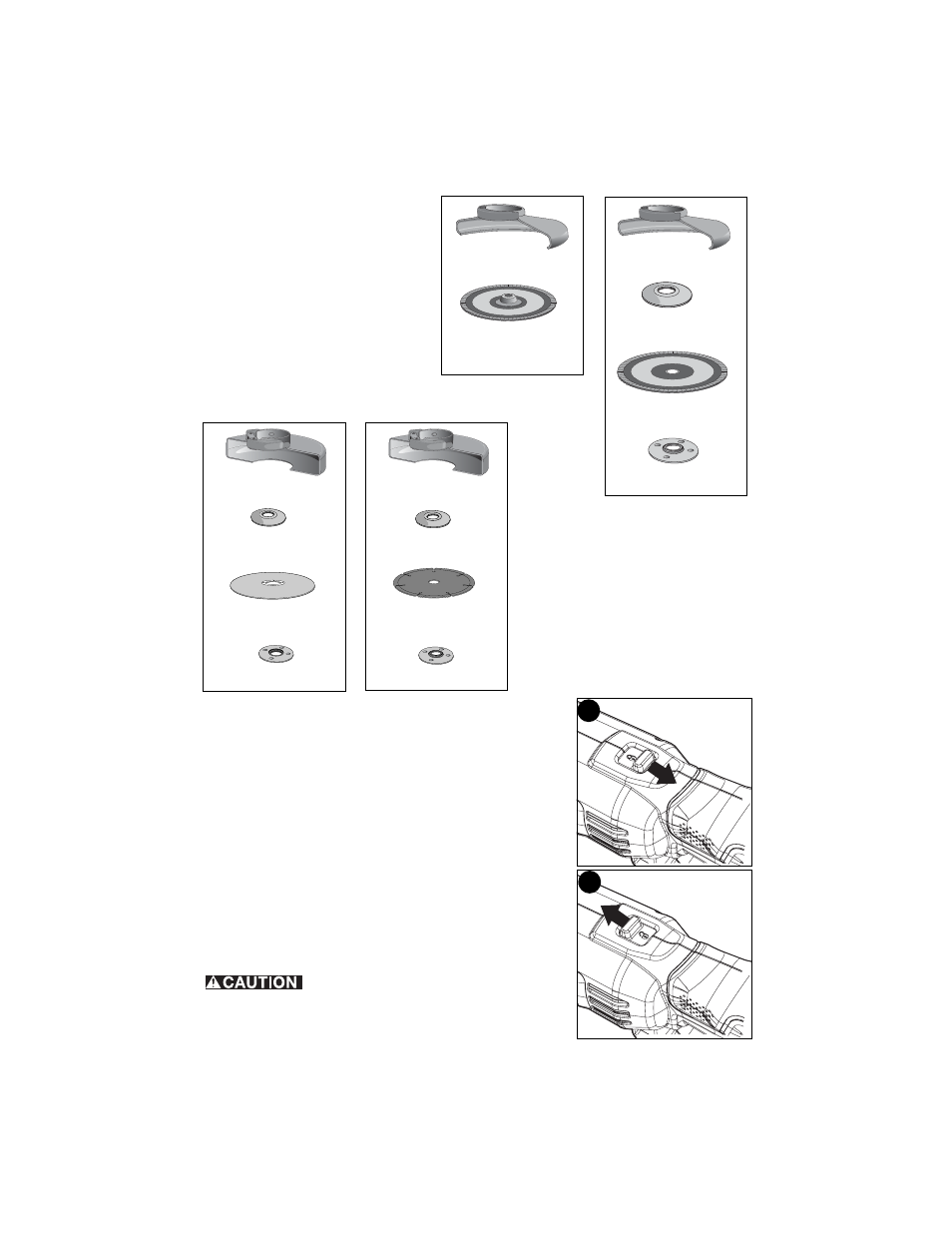
Switch (Figure H &I)
Lock-off Button and Trigger Switch
Your cut-off tool is equipped with a lock-off button (2).
To lock the trigger switch (1), move the lock-off button (2) to
the rear as shown in Figure H. When the lock-off button is
moved to this position, the trigger switch is locked.
Always lock the trigger switch when carrying or storing the
tool to eliminate unintentional starting.
To unlock the trigger switch, move the lock-off button to the
front as shown in Figure I . When the lock-off button is moved
to this position, the trigger switch is unlocked.
Pull the trigger switch (1) to turn the motor ON. Releasing the
trigger switch turns the motor OFF.
NOTE: This tool has no provision to lock the switch in the ON
position, and should never be locked ON by any other means.
Hold the side handle (5) and body of the
tool firmly to maintain control of the tool at start up and
during use and until the wheel or accessory stops rotating.
4-1/2 inch (115mm) Cutting Wheels
Type 1 guard
backing flange
abrasive cutting wheel
clamp nut
Type 1 guard
backing flange
diamond cutting wheel
clamp nut
4-1/2 inch (115mm) Sanding Flap Discs
hubbed sanding
flap disc
unthreaded backing
flange
non-hubbed sanding
flap disc
threaded clamp nut
Type 27 guard
Type 27 guard
:
H
I