Premier Mounts PWM-F110 User Manual
Page 15
PWM-F110
Page - 15 -
Installation Manual
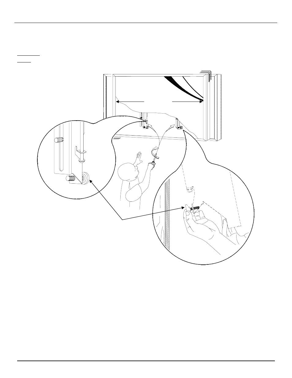
2.
Make any lateral shift adjustment and lock it by tightening the two (2) ¼”-20 Phillips screws found on
the bottom of the mounting brackets. Use the wall bumper to adjust your flat panel.
CAUTION:
Do not over tighten the ¼”-20 screws to the rods (Figure 16).
NOTE
:
To remove the flat panel from the wall, simply back off the ¼”-20 screws using a Phillips
screwdriver and lift the unit of the wall carefully.
Figure 16
Wall Plate
Wall
Bumper