Standard hookup, Wire recommendations – Polk Audio LSiM User Manual
Page 11
For more information visit our website at www.polkaudio.com
11
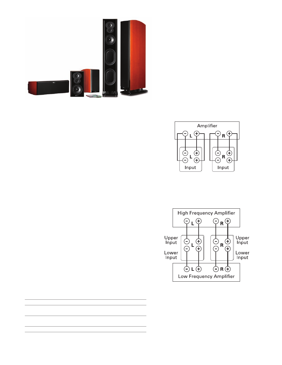
Standard Hookup
Bi-Wiring & Bi-Amping
If you decide to bi-wire or bi-amp, you
must remove
the jumpers between the terminal posts. Failure to do
this could result in damage to your amplifier and loud-
speakers. The binding post caps must be completely
removed to remove the jumpers, which use ring terminals.
There are color coded collars so you can identify which
is (+) or (–) after you remove the caps.
Bi-Wiring (see Figure 1)
Bi-wiring can provide noticeable improvements in the overall
transparency of your loudspeakers. Run separate speaker wires
to the low and high frequency drivers from a single amplifier
(the upper set of binding posts are for the high frequency drivers,
the lower set of binding posts are for the low frequency drivers):
after removing the jumpers, connect one set of speaker wires
to the upper terminals on each speaker and one set of wires
to the lower terminals. Connect the other ends of both wire
sets to the same amplifier outputs.
Bi-Amping (see Figure 2)
Bi-amping allows you to use separate amplifiers for the high and
low frequency sections of your loudspeaker for greater dynamic
range and lower distortion. We recommend that your separate
amplifiers have identical gain to preserve the speaker’s voicing
balance. After removing the jumpers, connect the speaker wires
from the high frequency amplifier outputs to the upper set of
terminal posts on each speaker. Follow the same procedure
for connecting the low frequency amplifier outputs to the
lower set of terminals. Remember to maintain correct wiring
polarity (+ to +, – to –) in all connections.
Wire Recommendations
These recommendations are for all connections
from the amplifier/receiver to each speaker:
Runs
Gauge
Lengths up to 25' 16 or better
Lengths greater than 25'
14
but less than 50'
Lengths greater than 50'
12
but less than 75'
Lengths greater than 75'
12
Figure 1: Bi-Wiring
Figure 2: Bi-Amping