Patton electronic MODEL 552 User Manual
Page 6
3.0 INSTALLATION
Patton's Model 552 is easy to install and should give you years of
trouble-free service. Here are a few simple instructions to help you get
things hooked up right.
1. Unplug (disconnect) the existing connection between the network
cable and the equipment’s I/O port.
2. Install the Model 552 between the incoming network cable and the
protected equipment using the 6 inch (15.2cm.) modular patch
cable (supplied). Place the surge protector as close as possible to
the device being protected.
NOTE:To ensure proper operation of the Model 552, make sure
that your equipment is connected to the protected side of the
Model 552. See Figure 1 below.
NOTE:The Model 552-E1 CX has two pairs of BNC jacks that
connect one to one through the device. See Figure 2 below.
3. Connect the braided ground strap directly to a chassis ground
connection on the protected device. If you are not sure where to
locate a chassis ground connection on your equipment, consult the
equipment's user manual or contact the manufacturer. Correct
ground connection is critical for proper operation of the Model 552.
APPENDIX A
MODEL 552 SPECIFICATIONS
General
Series Resistance:
0.340 Ohms
In Line Fuse Rating:
250V, 3/4A, 2.95 (A
2
sec) Nominal Melting
Point
Approvals:
CE (EMC Directive/EN 50082-1)
Connectors:
Two female RJ-45 or 4 BNC jacks
Model 552-DDS
Pins Protected:
Pins 1, 2, 7, 8
Clamping Voltage:
62 Volts in 500 nsec
Surge Capacity:
1500 Watts for 1 msec;
400A with an 8/20 μsec pulse
Protection Mode:
Common Mode Pins 1, 2, 7, 8 to shielding
braid
Differential Mode:
Pins 1, 2, 7, 8
Model 552-D2
Pins Protected:
Pins 4, 5 on the RJ-45 Interface;
Pins 3, 4 on the RJ-11 Interface
Clamping Voltage:
310 Volts in 500 nsec
Surge Capacity:
1500 Watts for 1 msec;
250A with an 8/20 μsec pulse
Protection Mode:
Common Mode Pins 4, 5 to shielding
braid
Differential Mode:
Pins 4, 5
Model 552-D4
Pins Protected:
Pins 3, 4, 5, 6 on the RJ-45 Interface
Pins 2, 3, 4, 5 on the RJ-11 Interface
Clamping Voltage:
310 Volts in 500 nsec
Surge Capacity:
1500 Watts for 1 msec;
250A with an 8/20 μsec pulse
Protection Mode:
Common Mode Pins 3, 4, 5, 6 to shielding
braid
Differential Mode:
Pins 3, 4, 5, 6
5
6
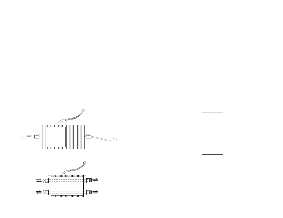
UNPROTECTED
PROTECTED
Figure 1. How to Connect the Model 552
Figure 2. Model 552-E1CX One to One Connection
TX and
RX from
network
TX and RX to
protected
equipment
Output to protected
equipment
Input from
network
Connection to
frame ground