Parker Hannifin EC106 User Manual
Page 7
Power Amplifier f. Pressure-/Flow Valves
Series EC106
Installation Manual
IA EC106 UK.INDD RH 02.06
7
Parker Hannifin GmbH & Co. KG
Hydraulic Controls Division
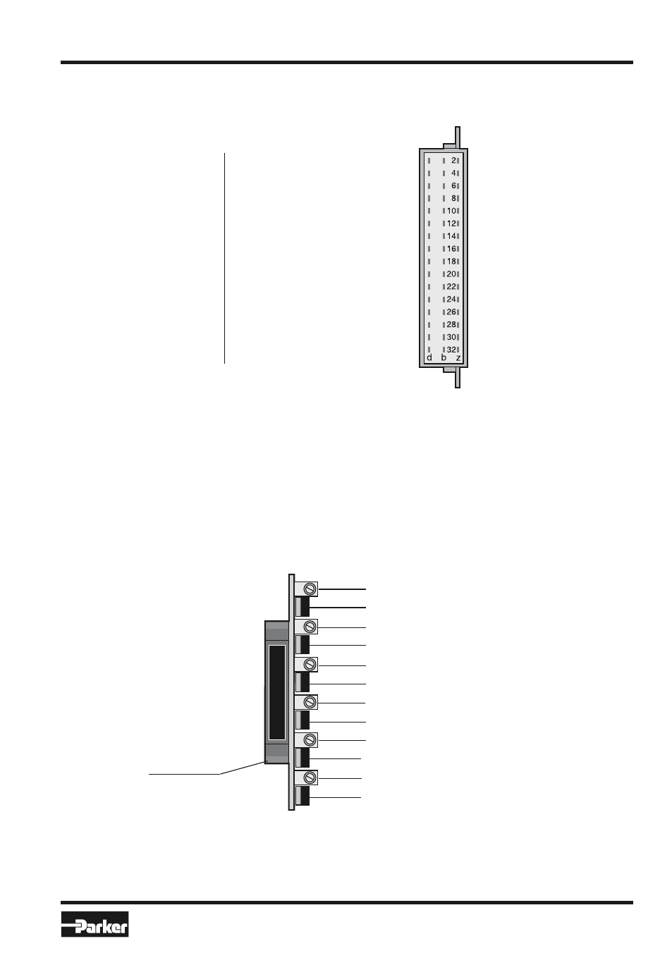
Operating and Diagnostic Elements
(Elevation A)
z2 0V Supply
z4 0V Command 1
z6 0V Supply
z8 0V Command 2
z10 0V Supply
z12 0V Command 3
z14 0V Command 4
z18 0V Command 5
z20 0V Supply
z22 0V Command 6
z24 0V Reference output
z26 0V Reference output
z30 Input 24VDC supply
z32 Input 24VDC supply
Connector (Elevation B)
d2 Output solenoid 1
d6 Output solenoid 2
d10 Output solenoid 3
d16 Output solenoid 4
d20 Output solenoid 5
d26 Output solenoid 6
d30 Output +10V reference
d32 Input 24VDC supply
b2 Output solenoid 1
b4 Input command 1 / 0...+10V
b6 Output solenoid 2
b8 Input command 2 / 0...+10V
b10 Output solenoid 3
b12 Input command 3 / 0...+10V
b14 Input command 4 / 0...+10V
b16 Output solenoid 4
b18 Input command 5 / 0...+10V
b20 Output solenoid 5
b22 Input command 6 / 0...+10V
b26 Output solenoid 6
b30 Output +10V reference
b32 Input 24VDC supply
Notes:
Turn off the electrical power to
the board whenever removing
it from the card holder.
Black grip strip
1 Ramp potentiometer channel 1
2 Switch p/Q channel 1
3 Ramp potentiometer channel 2
4 Switch p/Q channel 2
5 Ramp potentiometer channel 3
6 Switch p/Q channel 3
7 Ramp potentiometer channel 4
8 Switch p/Q channel 4
9 Ramp potentiometer channel 5
10 Switch p/Q channel 5
11 Ramp potentiometer channel 6
12 Switch p/Q channel 6