Switch lockout, Vise, Angle cutting – Porter-Cable 909516 User Manual
Page 7
7
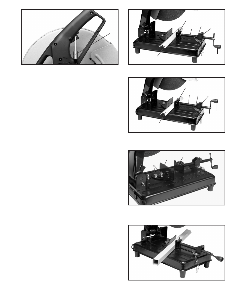
SWITCH LOCKOUT
IMPORTANT: When the tool is not in use, the switch
should be locked in the “OFF” position to prevent
unauthorized use, using a padlock (C) Fig. 7 with a 3/16"
diameter shackle.
Fig. 7
VISE
Clamping the workpiece can be accomplished quickly
and easily, as follows:
1.
Depress lever (A) Fig. 8, to lift half-nut (B) off screw
(C).
2.
Pull out screw handle (D) Fig. 8, far enough to allow
workpiece (E) to be placed in vise opening against rear
vise clamp, as shown. NOTE: It is not necessary to
thread the screw (C) when the half-nut (B) is in the up
position. The screw handle (D) can be pulled out or
pushed in.
3.
Push in on screw handle (D) Fig. 9, until front vise
clamp (F) contacts workpiece (E).
4.
Rotate lever (A) Fig. 9, to engage half-nut (B) with
screw (C) and tighten screw handle (D) to securely clamp
workpiece in vise.
Fig. 8
Fig. 9
Fig. 11
Fig. 10
ANGLE CUTTING
1.
Loosen two screws (G) Fig.10, and rotate rear vise
clamp (H) to the desired angle. Then tighten the two
screws (G). The front vise clamp (F) pivots on its post
and will automatically align itself with the workpiece.
2.
Fig. 11 illustrates a workpiece clamped in the vise
for a typical angle cutting operation.
C
A
B
C
D
E
F
A
D
B
C
F
E
G
H
F