Linksys PERFORMER SS210 User Manual
Page 7
7
A
B
D
L
†E
†E
K
C
H
I
J
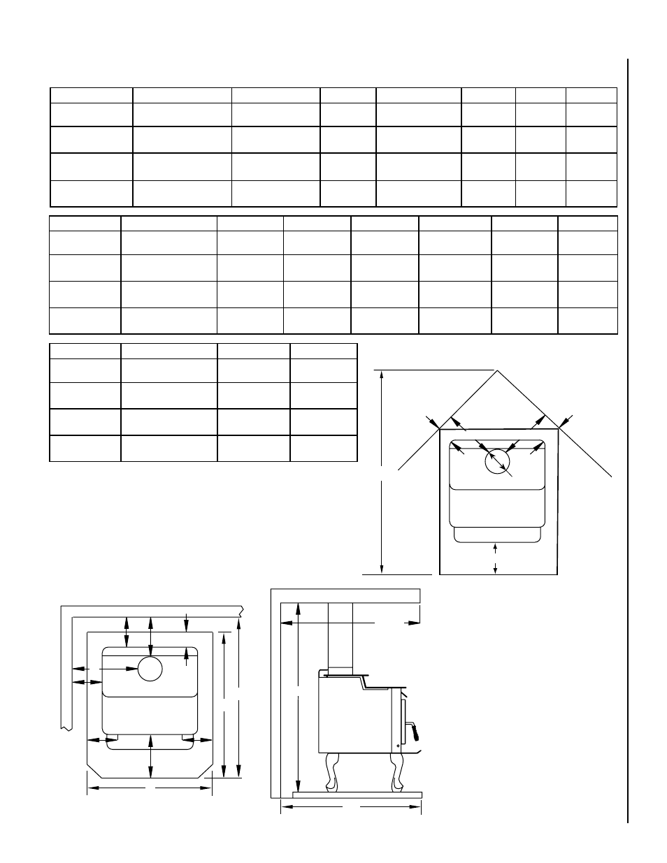
Floor Protection
FLOOR PROTECTION
I
M
F
F
T
Floor
Protection
G
G
K
48”
Max.
Depth
Diagram C: Top View
Corner Clearance, Stove and Flue to Wall
NOTE: DIAGRAMS & ILLUSTRATIONS ARE NOT TO SCALE.
6” Ø Flue Collar
PIPE
INSTALLATION
A
B (1)
C
D (1)
E†
F (1,4)
Single Wall
Residential
USA-16”
CAN-48mm
1-/4”
49mm
USA-4”
CAN-65mm
14-1/”
68mm
8”
00mm
9”
9mm
Single w/ Pipe
Shield
Residential
USA-10”
CAN-0mm
7-/4”
197mm
USA-4”
CAN-65mm
14-1/”
68mm
8”
00mm
9”
9mm
Double Wall
Residential or
Mobile Home*
USA-10”
CAN-0mm
7-/4”
197mm
USA-18”
CAN-48mm
8-1/”
16mm
8”
00mm
6”
15mm
Double Wall
Alcove
USA-10”
CAN-0mm
7-/4”
197mm
USA-1”
CAN-559mm
8-1/”
16mm
8”
00mm
6”
15mm
PIPE
INSTALLATION
G (4)
H ()
I (6)
J ()
K
L (5)
Single Wall
Residential or Alcove
USA-18”
CAN-5mm
USA-7-/4”
CAN-11mm
USA-51”
CAN-14mm
USA-4-/4”
CAN-1048mm
USA-16”
CAN-450mm
USA 0"
CAN-00mm
Single w/ Pipe
Shield
Residential or Alcove
USA-18”
CAN-5mm
USA-7-/4”
CAN-11mm
USA-45”
CAN-170mm
USA-4-/4”
CAN-1048mm
USA-16”
CAN-450mm
USA 0"
CAN-00mm
Double Wall
Air-Cooled
Residential or Alcove
or Mobile Home*
USA-15”
CAN-450mm
USA-7-/4”
CAN-11mm
USA-45”
CAN-170mm
USA-4-/4”
CAN-1048mm
USA-16”
CAN-450mm
USA 0"
CAN-00mm
Double Wall
Alcove
N/A
USA-7-/4”
CAN-11mm
USA-45”
CAN-170mm
USA-4-/4”
CAN-1048mm
USA-16”
CAN-450mm
USA 0"
CAN-00mm
Installation Clearances - Refer to Diagrams A, B and C
Footnotes:
1- These dimensions to the stove body are
for reference only. Actual distances should
be measured from the stove’s flue collar.
2- Minimum noncombustible hearth pad
dimensions.
3- Shield shall be attached to the rear of the
stove pipe with a 1” air space and must run
from the top of the stove to the ceiling.
4- Not applicable to alcove installations.
5- In corner applications, when installed
at minimum back wall clearances, the
required floor protection is dimensioned
off the back plane of the stove, therefore
the floor protection required off the back
corners (at a 45 degree angle) only needs
to extend to the wall. This situation will
only occur in CANADA installations.
6- Reference dimension only, to assist in
planning the installation.
Clearances to connector pipe shall be mea-
sured from the flue collar of the stove.
† USA=8" (00mm) from door opening, Canada=8"
(00mm) from sides and back of unit
u
Dimensions to Stove Body
* Mobile Home - USA only
Diagram A: Top View-Parallel Installation
Diagram B: Side View-
Alcove and Parallel
Installations
PIPE
INSTALLATION
M
T (6)
Single Wall
Residential or Alcove
84”
14mm
USA-61-/4”
CAN-1619mm
Single w/ Pipe
Shield
Residential or Alcove
84”
14mm
USA-61-/4”
CAN-1619mm
Double Wall
Air-Cooled
Residential or Alcove
or Mobile Home*
7”
189mm
USA-57-1/”
CAN-177mm
Double Wall
Alcove
7”
189mm
USA-57-1/”
CAN-177mm