Lathem DDC2 User Manual
Page 43
Page 37
Digital Display Wall Clock Guide
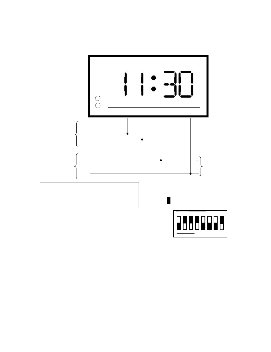
DDC2 / 4-RS Wiring
Cincinnati D6, Edwards 2406
AB
PC
Y
E
L
/
W
H
T
GRND
AC IN
AC RTN
B
L
K
B
L
K
V
IO
/
W
H
T
To
Other Clocks
24-36VDC
From
Master Clock
115VAC
Local
Power
OPEN
1
2
3
4
5
6
7
8
Set switches 1-5 of SW1 as
shown.
Indicates depressed side of
Set switches 1-5 of S1 as shown.
Indicates depressed side of switch
H
M
Clock must be set within 20 minutes of actual time
for master to synchronize. Use of a 9Volt alkaline
battery is recommended to avoid resets after power
failures.