Installation, Electrode and work cable connections, Caution – Lincoln Electric POWER WAVE IM718 User Manual
Page 13: Cable inductance, and its effects on pulse welding
A-6
INSTALLATION
POWER WAVE AC/DC
A-6
ELECTRODE AND WORK CABLE
CONNECTIONS
Due to the PowerWave AC/DC
’
s ability to produce either
a DC positive, DC negative or AC output the electrode
and work connections do not need to be reversed for the
different polarities. Additionally no DIP switch changes
are required to switch between the different polarities. All
of this is controlled internally by the Power Wave AC/DC.
The following directions apply to all polarities:
Connect a work lead of sufficient size (Per Table 1) and
length between the "work" stud (located beneath the
spring loaded output cover on the front of the machine)
and the work. For convenience, the work lead can be
routed behind the left strain relief (under the spring
loaded output cover), along the channels, and out the
back of the machine. Be sure the connection to the work
makes tight metal-to-metal electrical contact. The work
piece connection must be firm and secure. Excessive
voltage drops caused by poor work piece connections
often result in unsatisfactory welding performance, espe-
cially if pulse welding is planned. To avoid interference
problems with other equipment and to achieve the best
possible operation, route all cables directly to the work
and wire feeder. Avoid excessive lengths and do not coil
excess cable.
Connect the electrode cable between the wire feeder and
the "electrode" stud on the power source (located behind
the cover plate on the lower right side). For convenience,
the cable can be routed through the oval hole in the rear
of the machine before being connected to the output ter-
minals. Connect the other end of the electrode cable to
the wire drive feed plate. Be sure the connection to the
feed plate makes tight metal-to-metal electrical contact.
The electrode cable should be sized according to the
specifications given in (Table A.1).
Suggested Copper Cable Sizes - 100 Duty Cycle Combined
Length of Electrode and Work Cables (Table A.1)
Cable Length (ft (m) Parallel Cables
Cable Size
0 (0) to 100 (30.4) 1
4/0 (120mm
2
)
100 (30.4) to 200 (60.8) 2
2/0 (70mm
2
)
200 (60.8) to 250 (76.2) 2
3/0 (95mm
2
)
When using inverter type power sources like the
Power Wave, use the largest welding (electrode and
work) cables that are practical. When pulsing, the
pulse current can reach very high levels. Voltage
drops can become excessive, leading to poor welding
characteristics, if undersized welding cables are used.
NOTE: K1796 coaxial welding cable is recommended
to reduce the cable inductance in long cable lengths.
This is especially important when Pulse welding up to
350 amps.
CABLE INDUCTANCE, AND ITS EFFECTS
ON PULSE WELDING
For Pulse Welding processes, cable inductance will
cause the welding performance to degrade. For the
total welding loop length less than 50 feet, traditional
welding cables may be used without any effects on
welding performance. For the total welding loop length
greater than 50 feet, the K1796 Coaxial Welding
Cables are recommended.
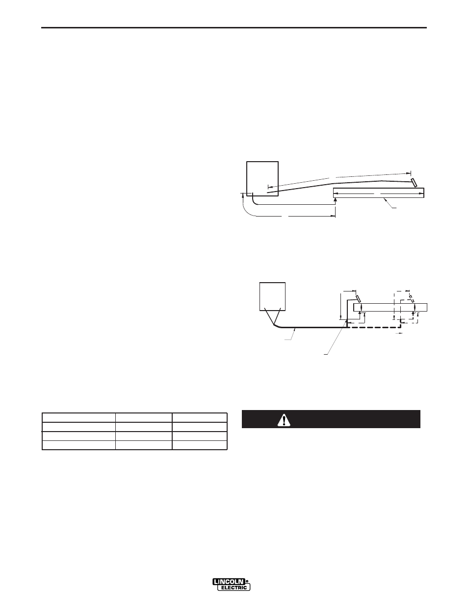
The welding loop length is defined as the total of elec-
trode cable length (A) + work cable length (B) + work
length (C) (See Figure A.3).
For long work piece lengths, a sliding ground should
be considered to keep the total welding loop length
less than 50 feet. (See Figure A.4.)
FOR A DETAILED CONNECTION DIAGRAM USING
K1796 COAXIAL CABLE, SEE PAGE F-4.
When pulsing, the pulse current can reach very
high levels. Voltage drops can become excessive,
leading to poor welding characteristics, if under-
sized welding cables are used.
------------------------------------------------------------------------
CAUTION
B
A
C
FIGURE A.3
POWER
WAVE
WORK
A
C
B
POWER
WAVE
FIGURE A.4
K1796 COAXIAL CABLE
MEASURE FROM END
OF OUTER JACKET OF
CABLE
C
A
B
WORK
SLIDING GROUND