LA Audio SPX20 User Manual
Page 6
Page 6
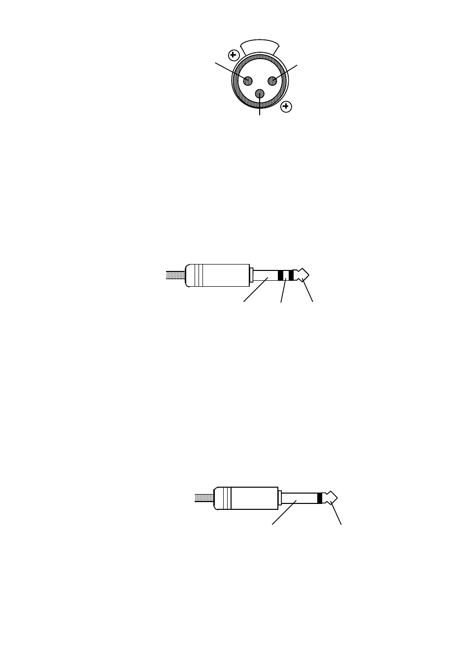
Pin 1 = Screen
Pin 2 = Hot (+)
Pin 3 = Cold (-)
PUSH
Fig 2.6.3: Pin arrangement for XLR inputs on the SPX20
Pin
1
Screen
Signal
ground
Pin
2
Hot
Signal
+
Pin
3
Cold
Signal
-
For unbalanced operation join pins 1 and 3 and connect to Screen (signal
ground) and use pin 2 as Hot (signal +).
Input 1 also has a pair of front panel inserts on TRS jacks which are wired
as follows -
Sleeve
Screen
Ring
Cold (-)
Tip
Hot (+)
Fig 2.6.3: Pin arrangement TRS jack inserts on Input 1
Tip
Hot
Signal
+
Ring
Cold
Signal
-
Sleeve
Screen
Signal
ground
For unbalanced operation join Ring and sleeve and connect to screen
(signal ground) and use Tip as Hot (signal +).
Plugging a mono jack into these inserts effectively unbalances the
connection.
Sleeve
Screen
Tip
Hot (+)
Fig 2.6.4: Mono jack pin arrangement
Tip
Hot
(signal
+)
Sleeve Screen (signal ground)