Lightolier 28702 User Manual
Instructions for attaching prospec, Adapter to prospec, Track for use with prospec
READ AND UNDERSTAND THESE INSTRUCTIONS BEFORE INSTALLING FIXTURE
This fixture is intended for installation in accordance with the National Electrical Code and local regulations.
To assure full compliance with local codes and regulations, check with your local electrical inspector before
installation. To prevent electrical shock, turn off electricity at fuse box before proceeding.
Retain these instructions for maintenance reference.
INSTRUCTION SHEET NO.
IS:28702
1299
Page 1 of 2
INSTRUCTIONS FOR ATTACHING ProSpec
®
ADAPTER TO ProSpec
®
TRACK
For use with ProSpec
®
Track Systems Only
LIGHTOLIER a GENLYTE company.
631 Airport Road, Fall River, MA 02720
®
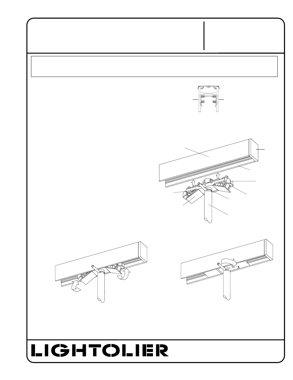
1. Select the CIRCUIT in ProSpec TRACK you want the
ProSpec SPOT to be powered with (Fig.1) by orienting the
LEVER towards the side of the TRACK of the selected
CIRCUIT. (Fig. 2)
2. With the CLAMPING TABS in the down position, insert
ADAPTER into ProSpec TRACK and flip the CLAMPING
TABS up to secure the ADAPTER. (Fig. 3)
3. To energize FIXTURE, turn LEVER all the way until LEVER
is parallel to ProSpec TRACK. (Fig. 4)
4. To remove FIXTURE, reverse procedure in Step 3 then flip
down CLAMPING TABS and pull FIXTURE out of ProSpec
TRACK.
DO NOT ATTEMPT TO RELEASE CLAMPING TABS
before disconnecting power with LEVER.
NEVER PLACE FINGERS ABOVE THE BARRIERS
ON THE CLAMPING TABS WHEN INSTALLING
OR REMOVING FIXTURE.
5. To change FIXTURE to second circuit, remove FIXTURE as
indicated in Step 4, then turn FIXTURE around 180° until
LEVER is pointing to the other side of ProSpec TRACK
and installed as indicated in Step 2.
INSTRUCTIONS FOR ATTACHING ADAPTER TO
ProSpec
®
TWO CIRCUIT TRACK
CIRCUIT 1
Fig. 1
Fig. 4
CIRCUIT 2
CIRCUIT 1
CIRCUIT 2
Fig. 2
Fig. 3
LEVER
CLAMPING
TABS
ProSpec TRACK
ADAPTER
TRACK
BARRIER
BARRIER
FINGER LOCATION
FOR REMOVAL