Locke TVM-3077 User Manual
Page 11
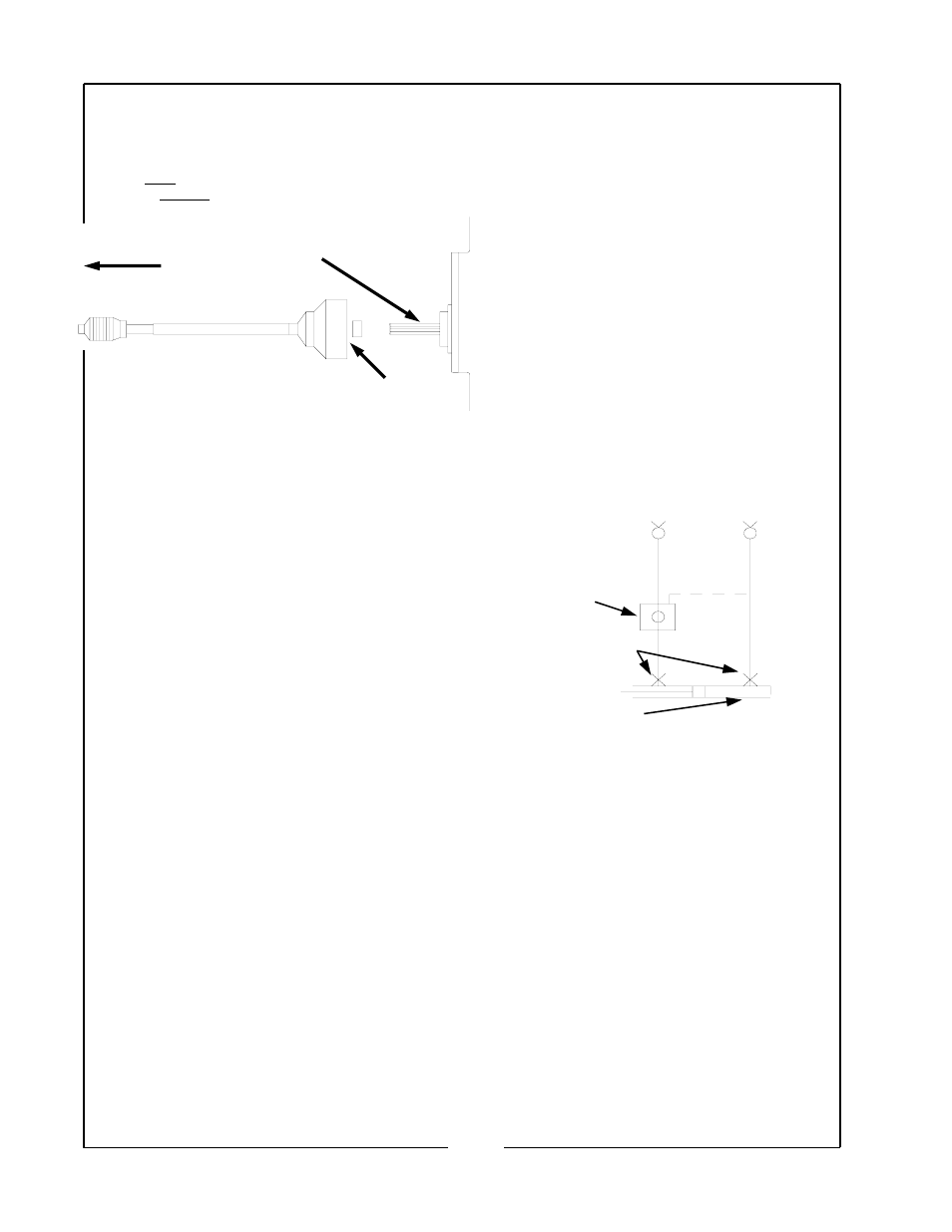
NOTE:
The “lift” hose runs into the port on the front of the check
(lock) valve.
The large (constant velocity U-joint) end of the shaft goes
on the tractor’s PTO shaft.
Belt Idlers – Main Drive
Check regularly for correct belt tension, particularly every 5
to 10 hours following installation of new belts. To adjust
belt idlers:
1. Remove belt guards.
2. Loosen idler clamping bolt.
3. Adjust idler to allow 3/4" to 1” up and down movement
of the bolt half way between sheaves.
4. Replace bolt guards.
Lift Chain Adjustment
The outer lift chains on mowing units #4 and #5 provide
adjustment of the nylon rollers in the snubbers and lift op-
eration. IF the #4 and #5 mowing units do not engage the
snubber ramps properly when lifting, adjust as follows:
1. Lower cutting units to the ground and loosen the nut
on the chain-adjusting rod and back off the nut several
turns.
2. Remove the clevis pin form the adjusting yoke.
3. Turn the adjusting yoke towards the nut to increase the
lift and decrease the roller clearance in the snubber.
4. Replace the yoke and clevis pin, making sure that the
chain is not twisted.
5. Lift the mowing units into place to check that adjust-
ment is correct when there is slight tension on the lift
chain and the nylon rollers are tight in the snubber.
6. When adjustment is correct, tighten the adjusting rod
locking nt. Insure also that the cotter pin is secure.
Cutting Unit Belt Adjustment
The cutting units on the Verti-Cutter are equipped with
heavy duty spring tensioning. For proper operation the
belts must be extremely tight. Tighter than is normally
recommended in other belt drive applications. Keep the
spring at no more than 2" in total length with the unit in
operating position and this should provide ample tension to
the belt. It will be necessary to check the spring length and
make recommended adjustments every 2 - 3 hours or as
needed. See diagram on page 16 of this manual.
Rear units will not climb onto snubbers:
PROBLEM
SOLUTION
1. Insufficient hydraulic
See tractor
Pressure
manual
2. Mechanical interference
Check to see that
no
moving
parts,
chains,
etc.
are
trapped
and
locked.
Units will not stay in raised position:
PROBLEM
SOLUTION
1. Leakage from hose
Tighten fittings.
Between check valve
replace fittings or
And cylinder
hose if necessary
replace
cylinder
seals.
Replace
cylinder if
necessary.
2. Leaking check
Replace check
valve
valve
Hydraulic
Plumbing
To lower the cutting units:
1.
Make sure the transport safety chain is un-
hooked and stowed on the left rear lift arm.
IMPORTANT:
DO NOT ATTEMPT TO LOWER THE CUTTING
UNITS WITH THE TRANSPORT SAFETY
CHAIN IN PLACE, AS THIS MAY RESULT IN
DAMAGE TO THE LIFT SYSTEM.
2.
Place the tractor’s external hydraulics control
valve in the “lower” position. Return the valve to the
center (neutral) position when the rear cutting unit lift
arms are fully down.
To raise the cutting units:
1.
Place the tractor’s control valve in the “lift”
position. Return the valve to the center (neutral) posi-
tion when the rear outer cutting units have fully en-
gaged snubbers.
Mower
Tractor PTO Shaft
Constant Velocity
U-Joint
Check (Lock)
Valve
Restrictor
Lift Cylinder
Pilot
Line
Pressure To
Lift
Pressure To
Lower
9