Life Fitness T9I User Manual
Page 6
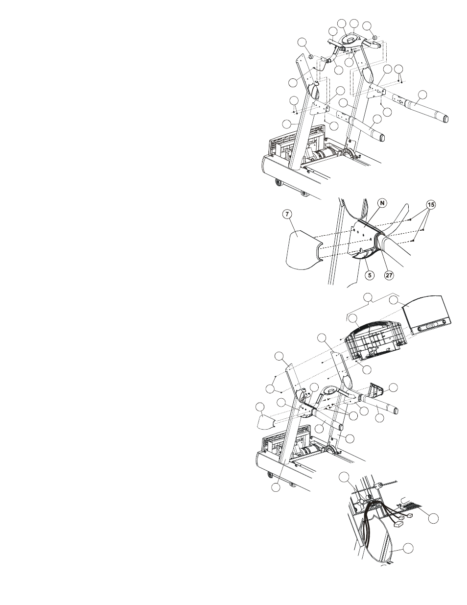
9.
Position the right end of the ERGO FRONT CROSSBAR (#4) near the
large access hole on the inside of the RIGHT UPRIGHT HANDLEBAR
BRACKET (L).
Align the ERGO FRONT CROSSBAR MOUNTING HOLES with those in
the RIGHT UPRIGHT HANDLEBAR BRACKET and secure using two
BOLTS (#19), from the inside of the treadmill, and NUTS (#22). Tighten
the BOLTS securely. Insert one SCREW (#16) from under the RIGHT
UPRIGHT HANDLEBAR BRACKET. Tighten the SCREW securely.
10.
Position the left end of the ERGO FRONT CROSSBAR (#4) near the
large access hole on the inside of the LEFT UPRIGHT HANDLEBAR
BRACKET (N).
Feed the HEART RATE CABLE (O) into the access hole downward out
the bottom of the LEFT UPRIGHT HANDLEBAR BRACKET.
Align the crossbar mounting holes with those in the LEFT UPRIGHT
HANDLEBAR BRACKET and secure using two BOLTS (#19), from the
inside of the treadmill, and NUTS (#22). Tighten the BOLTS securely.
Insert one SCREW (#16) from under the LEFT UPRIGHT HANDLEBAR
BRACKET. Tighten the SCREW securely.
NOTE: Be careful not to pinch the HEART RATE CABLE (O) when
assembling the ERGO FRONT CROSSBAR (#4) to the LEFT UPRIGHT
HANDLEBAR BRACKET.
Feed the HEART RATE CABLE (O) upward through the top of the LEFT
UPRIGHT (#1).
12.
Slide the LEFT INSIDE HANDLEBAR SHROUD (#5) near the LEFT
UPRIGHT HANDLEBAR BRACKET (N).
Locate and position the LEFT OUTSIDE HANDLEBAR SHROUD (#7) to
match the LEFT INSIDE HANDLEBAR SHROUD.
Secure the SHROUDS together using three SCREWS (#15). Tighten the
SCREWS securely. Do not overtighten the SCREWS. Repeat the
procedure for the RIGHT INSIDE and OUTSIDE HANDLEBAR SHROUDS
(#6 and #8).
13.
Locate the DISPLAY CONSOLE (#9). Remove the eight SCREWS (P) from
the back of the DISPLAY CONSOLE and separate the front of the DISPLAY
CONSOLE from the rear. Position the REAR CONSOLE (Q) over the LEFT
and RIGHT TOP MOUNTING PLATES (H & J) as shown. From the bottom
of the LEFT and RIGHT TOP MOUNTING PLATES, secure the REAR
CONSOLE using four screws (#17). Tighten the SCREWS securely. Do not
overtighten the SCREWS.
14.
Position and rest the FRONT CONSOLE (R) facedown across the
HANDLEBARS (#3). Connect all CONNECTORS leading from the LEFT
UPRIGHT (#1) to the corresponding CONNECTORS located on the FRONT
CONSOLE. Feed any excess WIRE HARNESS into the UPRIGHTS.
Carefully route all WIRE HARNESSES through the WIRE HARNESS
GUIDES (S) located at the lower left of the REAR CONSOLE (Q)
15.
Tilt the FRONT CONSOLE (R) upright and in position over the REAR
CONSOLE (Q). Secure the FRONT CONSOLE to the REAR using the
previously removed eight SCREWS (P). Tighten the SCREWS securely. Do
not overtighten the SCREWS.
NOTE: Be careful not to damage any wire harnesses when assembling the
FRONT CONSOLE (R) to the REAR CONSOLE (Q).
17
H
J
R
7
5
Q
8
P
6
15
N
3
3
2
1
9
Q
1
S
26
5
26
4
19
L
22
22
17
17
3
6
1
2
M
3
O
N