Installation – Lincoln Electric MAGNUM SG CONTROL MODULE IM398 User Manual
Page 12
INSTALLATION
Connection
to Power Source
Connect the control module to the power source using either a
K492-10, K493-10 or K691-10 Input Cable Assembly (ordered
separately), and follow the simple steps below.
Installation of K492-10 Input Cable to Power Sources with
a Terminal Strip
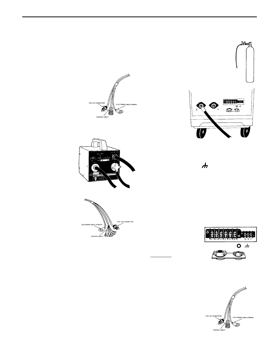
1. Identify the cable end which has the
Amphenol connector associated with it.
This end attaches to the Control Module.
2. Attach the control cable
Amphenol connector, gas
line connector, and elec-
trode cable terminal to
their respective connec-
tors on the rear panel of
the Control Module.
3. At the other end of the cable:
Connect the gas line to the gas cylinder
regulator
4. Connect the elec-
trode cable to the
positive(+) output
stud on the power
source.
5. Locate and open the access panel for the terminal strip on
the power source and connect the control cable:
a. Connect the terminal on the green-lead (marked “GND”)
to the ground screw ( ) on the chassis panel or
terminal strip.
b. Connect the white- and black-lead terminals marked “31”
and “32” to the corresponding 115 VAC terminals on the
terminal strip.
c. Connect the remaining two leads marked “2” and “4” to
the corresponding terminals which activate the output
contactor whether it be by switch closure or 115 VAC
supplied to the power source from the Control Module.
6. Set mode switch on
back of the Control
Module for the type of
contactor circuit in the
power source being
used. See “Setting the
Mode Switch on Rear
Panel”.
WARNING: Improper
switch position may
result in equipment
damage.
Installation of K493-10 Input Cable to Power Sources with
a 14-pin Connector
1. Identify the cable end which has a lug
on the end of the electrode cable. This
end attaches to the Control Module.
-12-