Section 1:assembly & set-up, Tractor requirements, Three-point hook-up – Land Pride 322-215M User Manual
Page 9: Pull type hook-up, Three point hitch assembly, Section 1: assembly & set-up, Three-point hook-up pull type hook-up, Warning, Table of contents tractor requirements
7
Section 1: Assembly & Set-up
5/29/13
Model SBR72 Seed Bed Roller 322-215M
Tractor Requirements
The tractor horsepower and weight must be capable of
controlling the Seed Bed Roller under all operating
conditions. Smaller horsepower and lighter weight
tractors must not be used.
Three-Point Hook-up
!
WARNING
Ballast weights may be required to maintain steering control.
Refer to your tractor’s operator’s manual to determine proper
ballast requirements.
A Category I hitch with 7/8" dia. holes in the lower hitch
links and 3/4" dia. hole in the top link is required. The
lower 3-point arms must be stabilized to prevent side-to-
side movement. Most tractors have sway blocks or
adjustable chains for this purpose. A Category II Land
Pride Quick Hitch can be used with the implement.
Horsepower requirements. . . . . . . . . . . . . . . 18 - 52 hp.
Minimum tractor weight . . . . . . . . . . . . . . . . . . 700 lbs.
Pull Type Hook-Up
The Pull Type Model is set-up with a 2" ball hitch and a
clevis type hitch.
Pull-type HP. . . . . . . . . . . . . . . . . . . . . . . . . . 18 - 50 hp.
Three Point Hitch Assembly
Refer to “Torque Values Chart For Common Bolt Size”
on page 21 when tightening hardware.
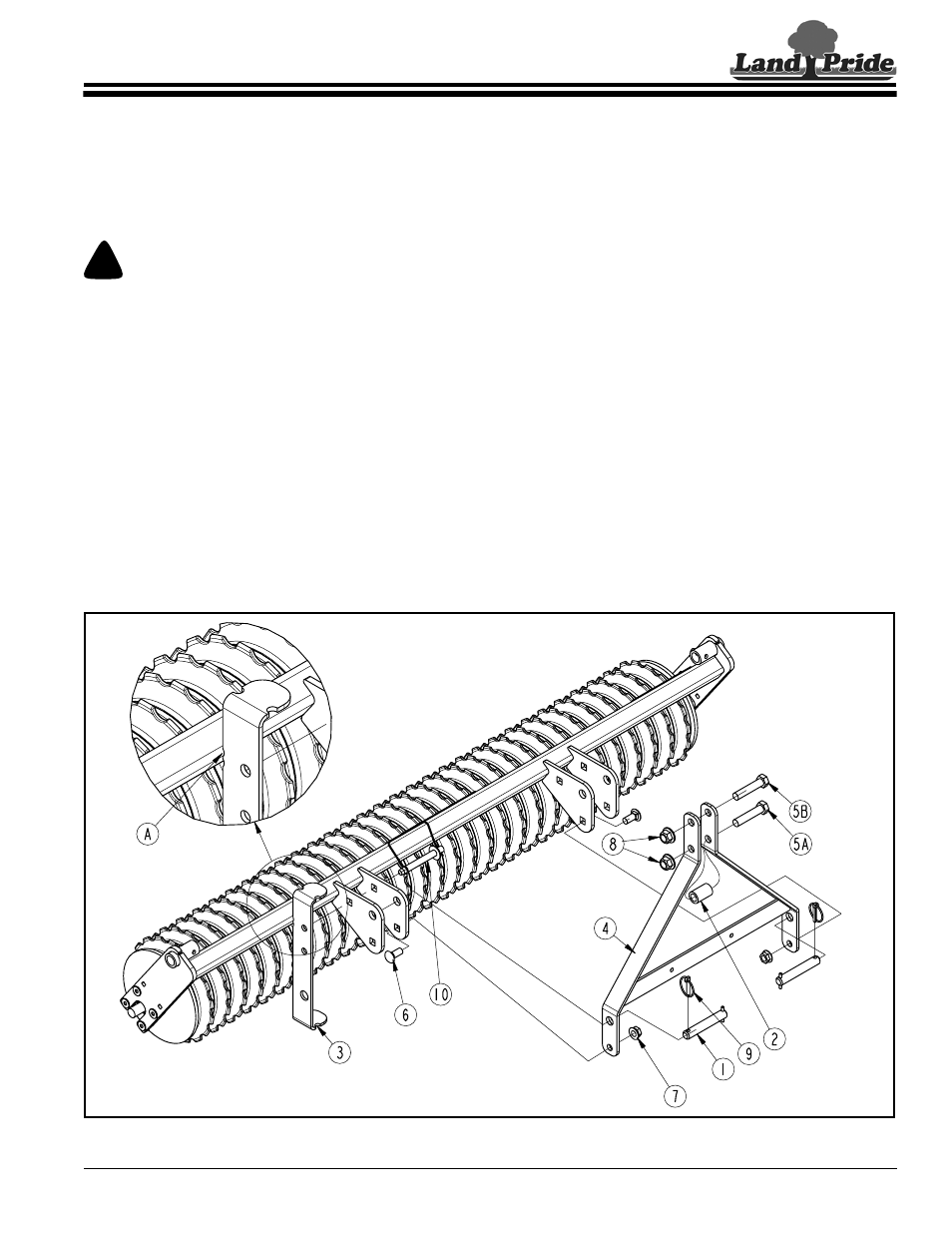
Refer to Figure 1-1:
1.
Chock front and back of rollers to prevent unit from
shifting while assembling the hitch assembly.
2.
Attach support stand (#3) to clevis plate with 5/8"
wire snap lock pin (#10). Make certain notch “A” is
located against the square tubing corner as shown.
3.
Attach bottom of hitch frame (#4) to clevis plates with
two 5/8"-11 x 1 1/2" GR5 round head square neck
bolts (#6) and 5/8" hex flange lock nuts (#7). Draw
nuts up snug, do not tighten.
4.
Attach upper two holes in hitch frame to clevis plates
with hitch pins (#1) and linch pins (#9)
5.
Install 3/4"-10 x 3 1/2" GR5 hex head cap screw
(#5A) with 1 1/4" x 2" spacer (#2) and 3/4" hex flange
lock nut (#7). Tighten nut to the correct torque.
6.
Install 3/4"-10 x 3 1/2" GR5 hex head cap
screw (#5B) and 3/4" hex flange lock nut (#8).
Draw nut up snug.
7.
Tighten 5/8" hex flange lock nuts (#7) to the correct
torque.
Section 1: Assembly & Set-up
Three point Hitch Assembly
Figure 1-1
25773