Kawasaki 840068 User Manual
Page 5
OPERATING INSTRUCTIONS
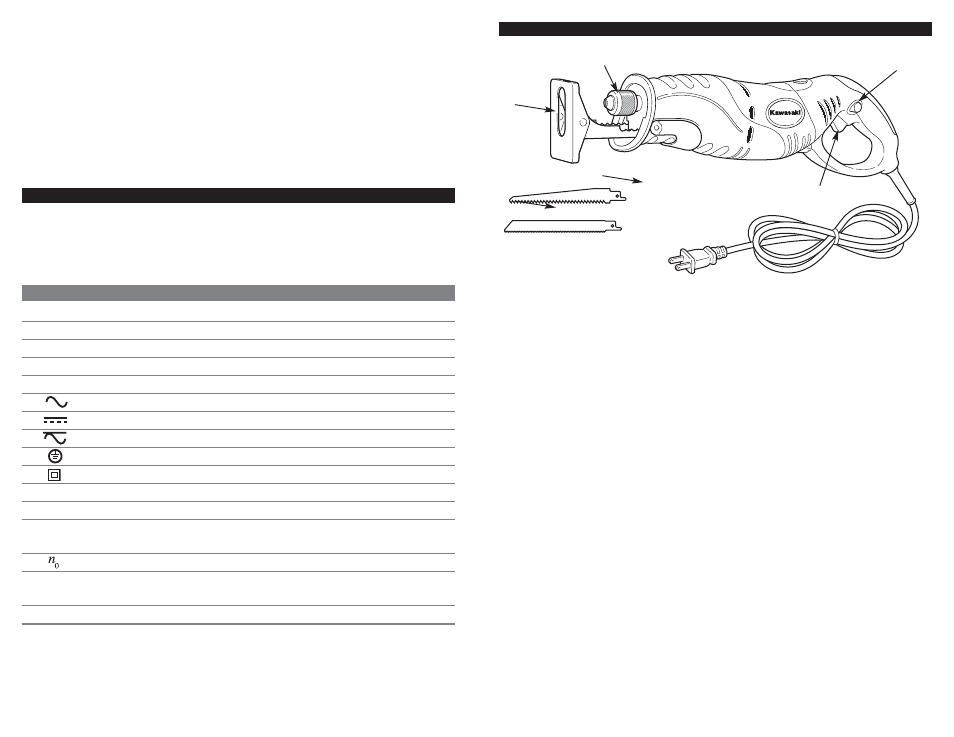
CONTROLS AND COMPONENTS:
1. Trigger Switch
2. Lock-On Button
3. Blade Clamp
4. Shoe
8
Use clamps (not included) or other practical ways to secure and support the
work piece to a stable platform. Holding the work by hand or against your body is
unstable and may lead to loss of control.
Maintain tools with care. Keep cutting tools sharp and clean. Properly maintained
tools with a sharp cutting edge are less likely to bind and are easier to control. Do
not use a damaged tool. Tag damaged tools “Do not use” until repaired.
Do not force the tool. Use the correct tool for your application. The correct tool
will do the job better and safer at the rate for which it is designed.
SYMBOLS
IMPORTANT: Some of the following symbols may be used on your tool. Please
study them and learn their meaning. Proper interpretation of these symbols will
allow you to operate the tool better and safer.
SYMBOL
NAME
EXPLANATION
V
Volts
Voltage (Potential)
A
Amperes
Current
Hz
Hertz
Frequency (Cycles per Second)
W
Watt
Power
Kg
Kilograms
Weight
Alternating Current
Type of Current
Direct Current
Type of Current
Alternating or Direct Current
Type of Current
Earthing Terminal
Grounding Terminal
Class II Construction
Denotes Double Insulation
min
Minutes
Time
s
Seconds
Time
Diameter
Size of Drill Bits,
Grinding Wheels, etc.
No load speed
No-load Rotational Speed
.../min
Revolutions per Minute
Revolutions, Surface Speed,
Strokes, etc. per Minute
1,2,3, …
Ring Selector Settings
Speed, Torque or Position Settings
7
ACCESSORIES:
5. Saw Blades (2)
6. Wrench
1
2
3
4
5
6