Kodak DCS 500 Series User Manual
Page 2
MODE
ISO
AF
W.BAL
DISP/MEN
U
SELEC
T
/ TAG
L
A
O
I
To insert a PC Card,
open the Battery/PC
Card door and insert.
With two cards, the first
card inserted is the
active card.
To select a different PC
Card, select the Folder
icon, then select the
card. (Refer to the
other side.)
Important!
Be sure the
Card Busy LED is off
before removing a PC
Card. The blinking
indicates data is being
transferred to or from
the PC Card. You can
lose data if you remove
a PC Card when it is busy.
To remove the PC Card, press the Eject
button.
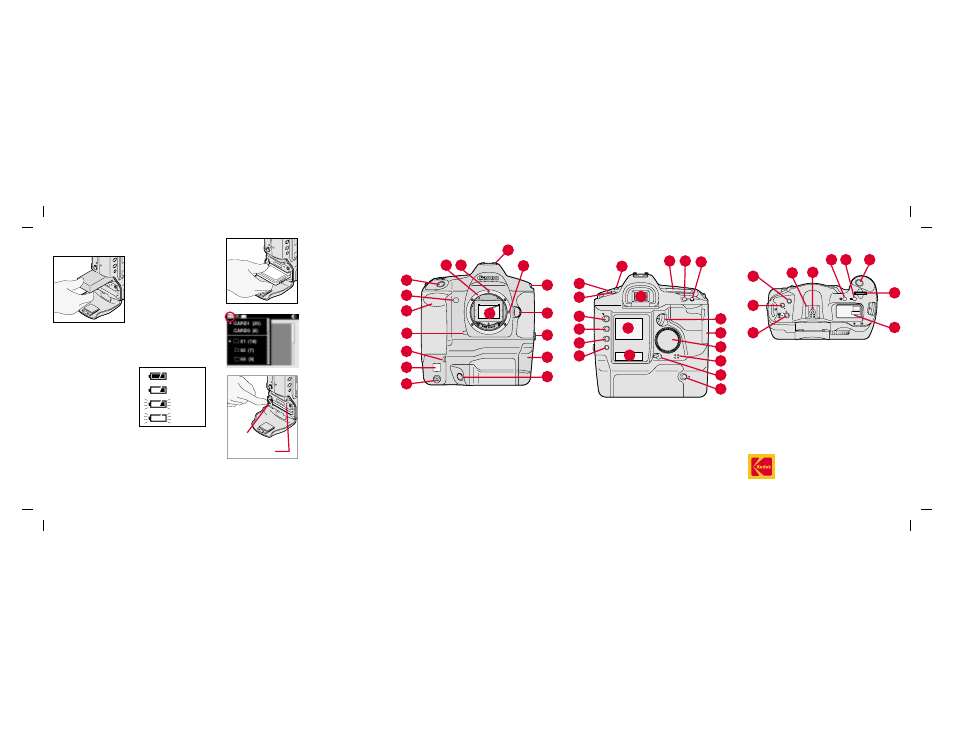
1. Lens Attachment Mark
(red)
2. Lens Mount
3. Shutter Button
4. Self-Timer Indicator
5. Palm Door (to access
Custom Functions)
6. Anti-aliasing or IR Filter
7. Depth-of-Field Preview
Button
8. Vertical Control Switch
9. White Balance Sensor
10. Canon Remote Port
11. X Contacts (for flash
attachments)
12. Lens Lock Pin
13. Strap Attachment
14. Lens Release Button
15. PC Terminal (Cover) for
flash sync (external)
16. Battery/PC Card Door (to
access battery and PC
Card)
17. Vertical Shutter Release
EASTMAN KODAK COMPANY
Rochester, New York 14650
© Eastman Kodak Company, 2000
Kodak and Kodak Professional are trademarks.
Printed in U.S.A.
P/N 6B5237
5/00
Camera
Front
2
3
4
5
6
7
8
9
10
11
12
13
14
15
17
Camera
Back
1
2
3
4
5
6
7
8
9
10
11 12 13
14
15
16
17
18
19
1. Shooting Mode Selector
2. AF Mode Selector
3. Metering Mode Selector/
Flash Exposure
Compensation Button
4. Viewfinder Eyepiece
5. Image Display
6. RECORD/TAG Button
7. DISP/MENU Button
8. SELECT Button
9. W. BAL Button
10. Back LCD Panel
11. Top LCD Panel
12. AE Lock Button
13. Focusing Point Selector
14. Quick Control Dial Switch
15. Palm Door
16. Quick Control Dial
17. Microphone
18. Main Switch
19. Vertical AE Lock Button
Camera Top
1
2
3
4
5
6
7
8
9
10
1. X Contacts
2. Accessory Shoe
3. Shooting Mode Selector
4. AF Mode Selector
5. Metering Mode Selector/
Flash Exposure
Compensation Button
6. LCD Panel Illumination
Button
7. Exposure Compensation
Button
8. Shutter Button
9. Main Dial
10. Top LCD Panel
Batteries
To power your camera,
open the Battery/PC
Card door, slide a
battery to the back of
the battery slot and
press firmly in place.
☛
You can also power your camera with an
AC adapter when working indoors or
connected to a computer.
Check the battery
icon on the Back
LCD panel.
PC Card
As you capture images, they are stored on
Type II or Type III PC Cards (PCMCIA cards)
in your camera.
There are two slots for PC Cards. You can
insert two Type II cards or one Type III card.
Full
1/2 Full
Low
Empty
16
Eject
button
Card Busy LED
1